Fiber-reinforced composite structure

a composite structure and fiber reinforcement technology, applied in the direction of roofs, weaving, transportation items, etc., can solve the problems of relative viscosity core materials that cannot rapidly fill the cavity, cannot rapidly and fully penetrate or impregnate fibrous layers, prior art composite structures tend to be relatively weaker than otherwise desired

Inactive Publication Date: 2001-12-18
SABIC GLOBAL TECH BV
View PDF54 Cites 81 Cited by
  • Summary
  • Abstract
  • Description
  • Claims
  • Application Information

AI Technical Summary

Benefits of technology

One advantage of the present invention is that the relatively low-viscosity core material includes a blowing agent that is activatable upon exposure to a predetermined vacuum pressure within the cavity to thereby rapidly fill the second region of the cavity with the foamed core material, and in turn create a relatively dense, resinous interface between each fibrous layer and the foamed core. Then, the catalytic reaction in the core material cooperates with the vacuum pressure within the cavity to create negative pressure gradients that cause the relatively dense, resinous interface formed between each fibrous layer and the foamed core to rapidly impregnate the fibrous layers, fill the first regions of the cavity, and bond the fibrous material to the polymeric sheet(s). As a result, the cycle times required to manufacture the composite structures of the present invention are significantly reduced in comparison to that of the above-described prior art processes and structures.
Yet another advantage of the present invention is that the preferred, relatively low viscosity core materials cooperate with the vacuum within the cavity to allow the resinous core to rapidly and fully impregnate (or "wet out") the fiber reinforcement layers, and in turn cause the composite structures of the present invention to be significantly stronger, and to have significantly improved strength-to-weight ratios in comparison to the above-described prior art structures. The composite structures of the present invention are therefore particularly advantageous for forming relatively large, thin-walled parts, in high volumes and in a commercially feasible manner, that exhibit improved strength in comparison to the above-mentioned prior art composite structures, as well as high-grade, cosmetically-appealing, impact and chemical resistant, and / or weatherable exposed surfaces. Accordingly, the composite structures of the present invention are particularly applicable to the manufacture of components for automobiles and trucks, including, for example, tonneaus for pick-up trucks, hard tops for automobiles and sports utility vehicles ("SUVs"), and other relatively large parts for trucks, vans and recreational vehicles.

Problems solved by technology

One drawback associated with these prior art structural composites, and methods of manufacturing such structural composites, is that the relatively viscous core materials cannot rapidly fill the cavity formed between the outer polymeric layers, and moreover, cannot rapidly and fully penetrate or impregnate the fibrous layers.
As a result, such prior art composite structures tend to be relatively weaker than otherwise desired and cannot be used to form primary structural parts or components.
In addition, such prior art composite structures and methods have not proven to be cost effective for manufacturing parts in substantial quantities due to the relatively high cycle times required to allow the foam to expand, fill the core, and penetrate the fibrous layers.
As production volumes increase, the complexity of the machinery involved, and the corresponding pressure applied to that machinery, necessarily increases.
Accordingly, when employing these prior art processes and composite structures, the size of a part that can be formed in relatively high volumes correspondingly decreases because of the processing difficulties associated with molding relatively large parts under relatively higher pressures.
However, this technology has not proven to be economically feasible for producing high volumes of parts, such as in excess of 5,000 parts.
Such processes, however, are generally limited to producing relatively smaller parts in comparison to the above-described processes.
Accordingly, one drawback associated with these and other prior art processes and associated structural composites is the inability to manufacture relatively large parts, such as parts having surface areas greater than about 25 square feet, in relatively high volumes, in a commercially feasible manner.
Another drawback associated with these and other prior processes and associated structural composites, particularly fiber-reinforced polymeric composites with foam cores, is the difficulty in forming relatively large, thin-walled products that retain the composite's strength as well as a high-grade, cosmetic, impact and chemical resistant, weatherable exposed surface.
However, application of an excessive amount of adhesive will lower the available surface area of the polymeric sheet 12, 12' for adhesively bonding with the polymeric core material 16.
Several characteristics of the fibrous material can affect its permeability, and therefore can affect this desired result.
Lastly, the fiber bundle stitch pattern also affects permeability.
In contrast, if the stitch pattern is such that the bundles are too loose, the desired strength characteristics may be diminished.

Method used


Image

  • Fiber-reinforced composite structure
  • Fiber-reinforced composite structure
  • Fiber-reinforced composite structure

Examples


Embodiment Construction

of the Polymeric Core Material

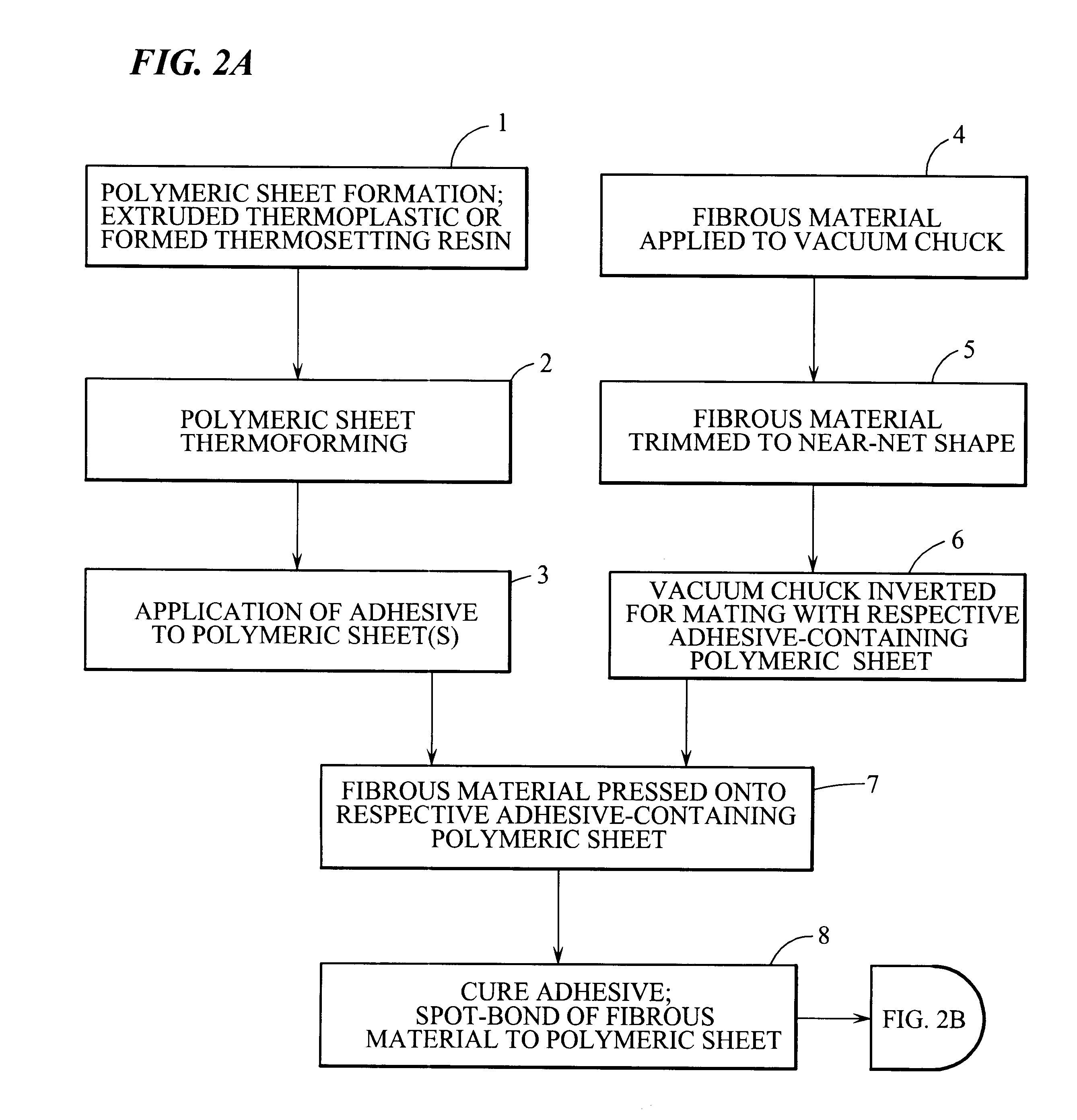
The process for producing a preferred embodiment of the polymeric core material 16 of the present invention comprises forming a polyurethane foam including:

i. Contacting a polyol mixture, an isocyanate, a blowing agent, and a catalyst to produce a reaction; and

ii. Expanding the reaction mixture to produce the polyurethane foam.

The first step in the process of the invention comprises provision of a reaction mixture comprising a polyol mixture, an isocyanate, a blowing agent, and a catalyst. As will be readily understood by one skilled in the pertinent art, the polyol mixture can be a single polyol, or can be a blend of two or more polyols. The exact chemical nature of each polyol is not particularly restricted. For example, the polyol can be made with one or both of ethylene oxide and propylene oxide, and may be a random or block polymer of one or more of polyoxypropylene diols, triols and tetrols, and ethylene oxide-capped diols, triols and tetrols. Gen...


PUM

PropertyMeasurementUnit
surface areasaaaaaaaaaa

Abstract

A fiber-reinforced composite structure has two molded outer polymeric layers spaced apart from each other and defining a cavity therebetween. Each molded outer polymeric layer defines a sealing surface extending about a periphery of the respective layer, and the opposing sealing surfaces cooperate to define a hermetic seal extending about a periphery of the cavity. One or more multi-directional fiber reinforcement layers are adhesively attached in a discontinuous manner to each outer polymeric layer, and define a first region of the cavity extending between each respective outer polymeric layer and adjacent fiber reinforcement layer, and a second region of the cavity extending between the fiber reinforcement layers. A core is located between the two outer polymeric layers, and is made of a resinous core material capable of exhibiting a foamed character and a resinous character. The resinous core material has a blowing agent activatable upon exposure to a predetermined vacuum pressure within the cavity to convert the core material within the second region of the cavity from a resinous character to a foamed character and thereby fill the second region of the cavity with the foamed core material. Each multi-directional fiber reinforcement layer is impregnated with the core material exhibiting a relatively dense, resinous character, and each first region of the cavity is substantially filled with the core material exhibiting a resinous character to fixedly secure the multi-directional fiber reinforcement layers to the outer polymeric layers. A structural insert, such as a rigid plate adapted to receive fasteners, is embedded within the core material for attaching other devices or structures thereto.

Description

The present invention relates to composite fiber-reinforced polymeric structures, and more particularly, to composite fiber-reinforced polymeric structures having at least two polymeric sheets in opposed spaced relationship such that a cavity is formed therebetween, at least one fibrous reinforcing layer bonded to the inner surface of at least one of the polymeric sheets, and a polymeric core material introduced under vacuum into the cavity between the polymeric sheets. The polymeric core material exhibits a resinous character in the region of the fibrous reinforcing layer to impregnate the fibrous layer and adhere the fibrous layer to the adjacent polymeric sheet, and exhibits a foamed character defined by a multiplicity of foam cells in the region on the opposite side of the fibrous layer relative to the polymeric sheet. The present invention is particularly suitable for forming relatively large composite structures, such as structural components for automobiles, trucks, recreatio...

Claims


Application Information

Patent Timeline
Patent Type & Authority Patents(United States)
IPC IPC(8): B29C44/12B29C44/02B29C70/08B32B5/22C08G18/66
CPCB29C44/1209B29C70/086B32B5/22C08G18/6674C08G2101/00Y10T428/24777Y10T428/24628Y10T428/233Y10T428/24612Y10T428/239C08G2105/02B29C44/14C08G2115/02Y10T428/249986Y10T442/20
Inventor O'NEILL, MICHAEL A.KIRK, WAYNE D.SIMMONS, STUART C.TRUDEAU, PAULBREMMER, JONATHAN W.
Owner SABIC GLOBAL TECH BV
Why Eureka
Try Eureka