

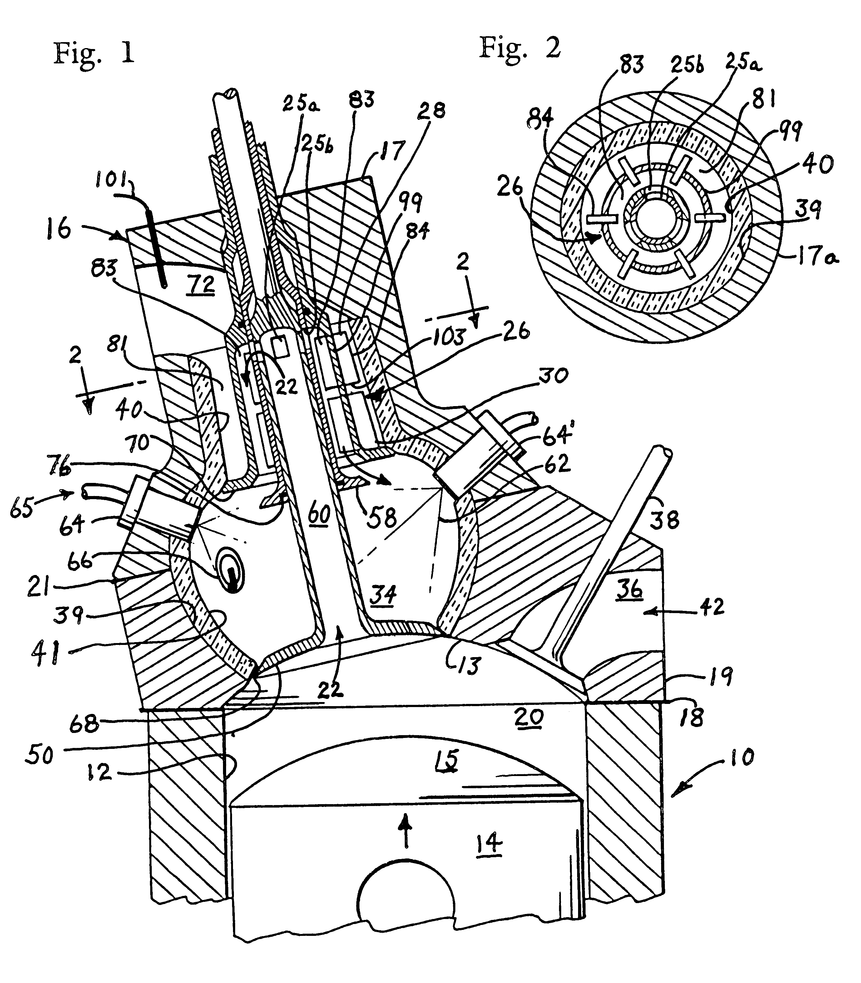
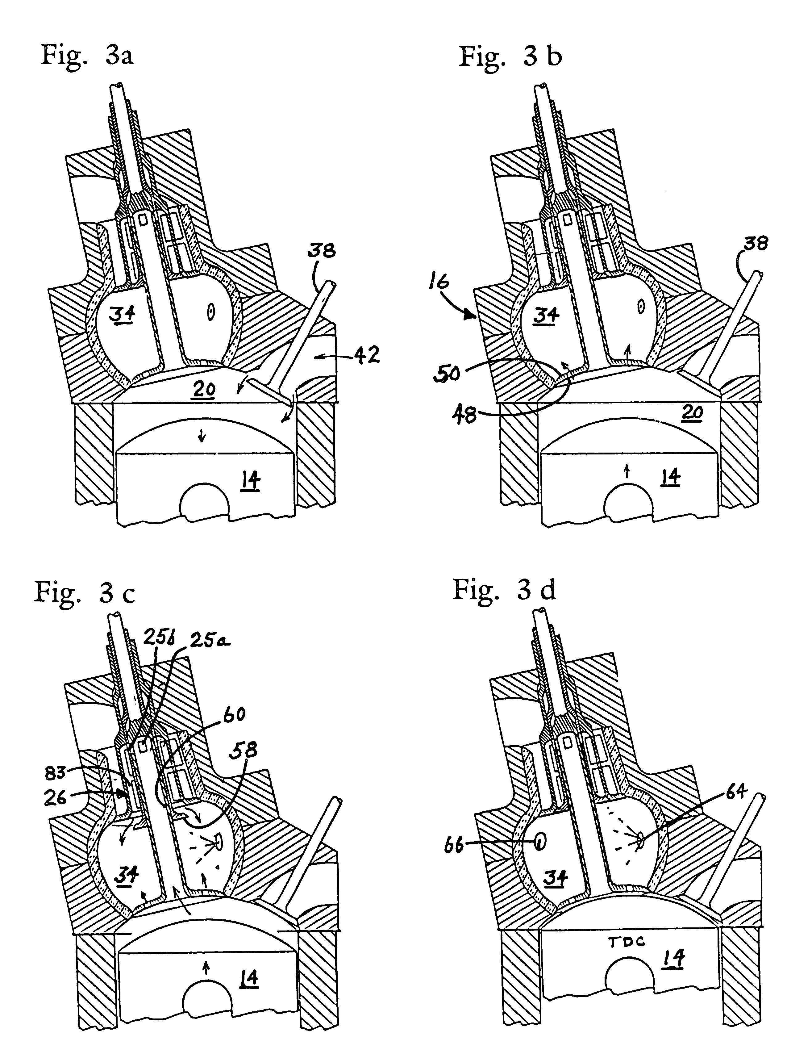
Four-stroke internal combustion engine with recuperator in cylinder head
a recuperator and internal combustion engine technology, applied in the direction of machines/engines, cylinders, mechanical equipment, etc., can solve the problems of increasing weight and cost, absorbing much heat, and increasing strength
- Summary
- Abstract
- Description
- Claims
- Application Information
AI Technical Summary
Benefits of technology
Problems solved by technology
Method used
Image


Examples
Embodiment Construction
During operation of the engine of FIG. 1, inlet valve 38 is opened as piston 14 starts to descend on a first stroke from top dead center towards bottom dead center, inducting a charge of ambient air as shown by arrow 42 through inlet duct 36 and into working volume 20 of cylinder 12. During the induction of ambient air, combustor valve 50 and recuperator valve 58 remain in a closed state. Inlet valve 38 also closes as piston 14 begins its second stroke and return to top dead center which compresses said air within cylinder 12. A small percentage of the air undergoing compression bleeds into combustion chamber 34 through multiple coolant passages 48 in valve 50. The remainder of the air undergoing compression is compressed in cylinder 12 against closed valves to a volume approximately equal to the combined volume of duct 60, recuperator 26, and combustion chamber 34 and then passed in a compressed state from working volume 20 through duct 60, past now open transfer valve 56, and then...
PUM
 Abstract
Description
Claims
Application Information