
Managing Vt for reduced power using a status table

a technology of status table and power reduction, applied in the direction of liquid/fluent solid measurement, sustainable buildings, instruments, etc., can solve the problems of consuming greater static power, less static power, and providing lower performan

Inactive Publication Date: 2002-02-05
GLOBALFOUNDRIES INC
View PDF20 Cites 149 Cited by
  • Summary
  • Abstract
  • Description
  • Claims
  • Application Information

AI Technical Summary

Benefits of technology

For example, assume an IC embodying the invention had functional units dedicated to floating point arithmetic functions and a modem and the application program or program segment being executed involved a remote file transfer but no floating point operations. One could optimize the performance and power consumption of the IC for this program or program segment by reducing the power consumed by the floating point arithmetic functional unit to a minimum and raising the power consumption of the modem-related unit(s). Raising of the power level in the modem-related unit(s) is justified by the increase in performance while the power savings on the floating point arithmetic functional unit is obtained at no cost since the absence of floating point arithmetic operations means the performance of that functional unit or units is of no consequence to the execution of the application or program segment.

Problems solved by technology

By increasing the body to source voltage, transistors achieve a higher threshold voltage, consume less static power but on the other hand provide lower performance.
Conversely, lowering the body to source bias voltage reduces the transistor threshold voltages, providing higher performance but consuming greater static power.
Notwithstanding the foregoing, the art lacks a technology to allow optimizing power management in light of the actual repertoire of instructions applied to a partitioned integrated circuit.

Method used


Image

  • Managing Vt for reduced power using a status table
  • Managing Vt for reduced power using a status table
  • Managing Vt for reduced power using a status table

Examples


Embodiment Construction

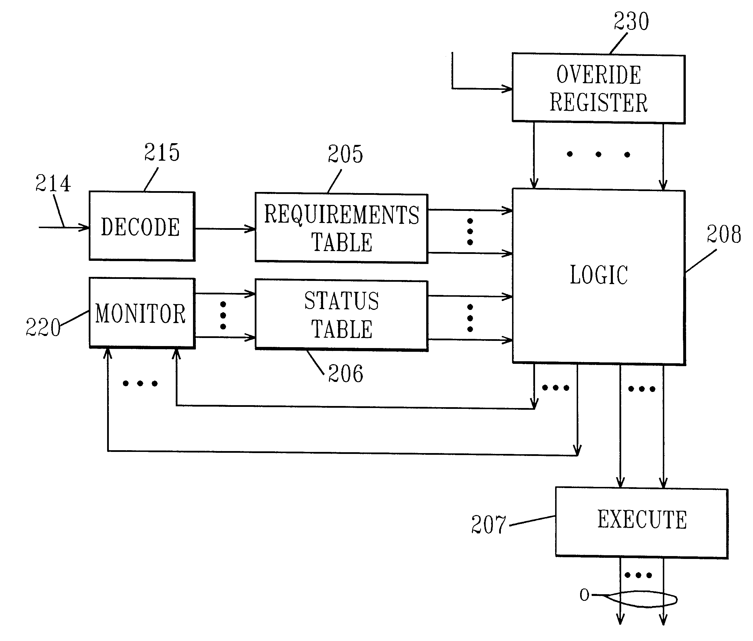
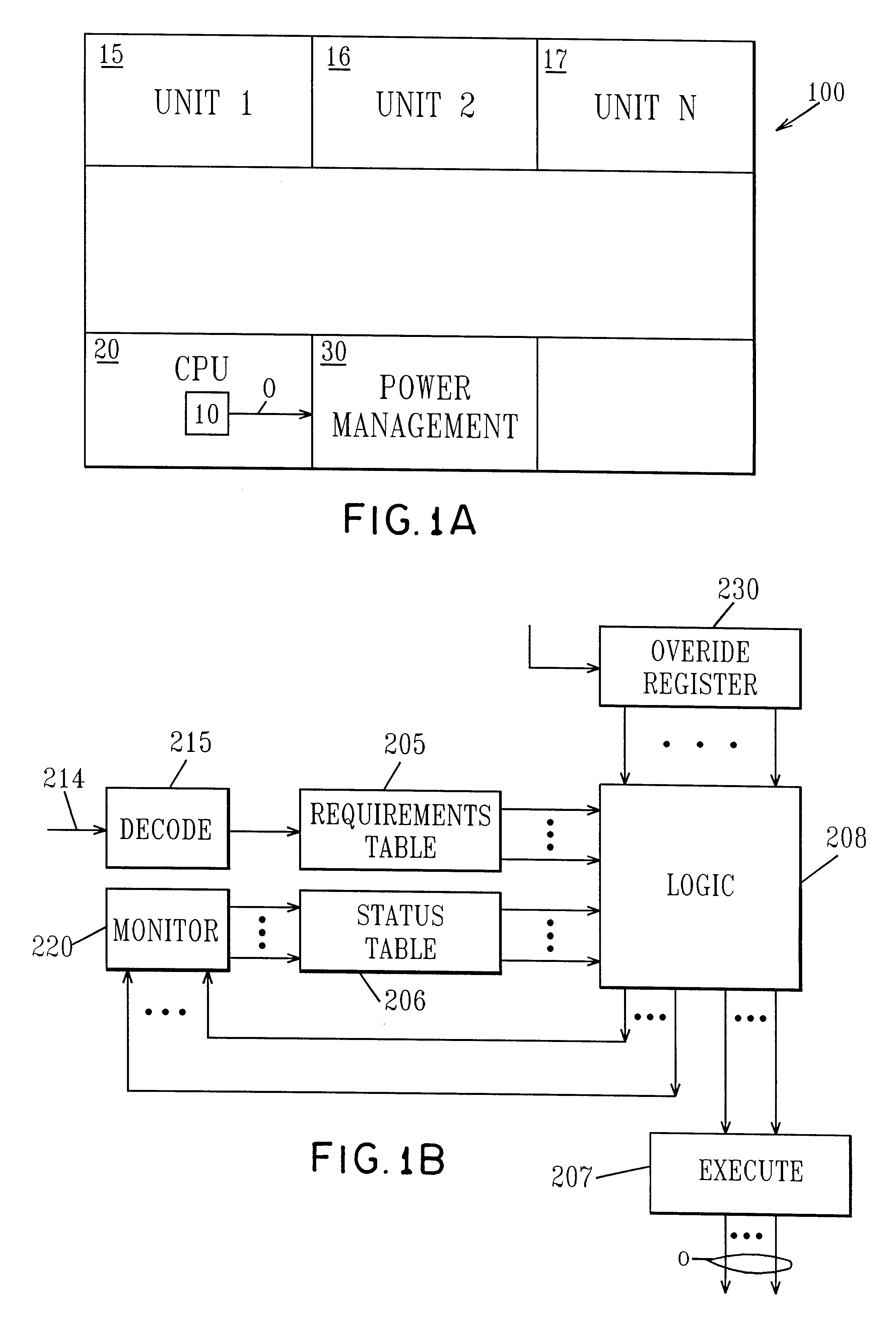
FIG. 1A is an illustration of a typical integrated circuit chip 100 which incorporates the present invention. The chip 100 includes a plurality of functional units such as units 15, 16 and 17. Units 1-n are representative of a plurality of functional units which are included on the integrated circuit 100. Typically the functional units perform different functions and are capable of operating at different threshold voltages (V.sub.t) where a higher threshold voltage represents a lower power consumption but at a slower speed of operation and a lower threshold voltage represents a higher power consumption but higher operating speed. As will be described, through the use of the method and apparatus of the invention the power consumption of the different functional units may be controlled so as to optimize operation of the chip as a whole in light of the specific instruction(s) which is or are presented for execution. It is the thesis of the present invention that some functional units o...


PUM


Abstract

An integrated circuit includes a CPU, a power management unit and plural functional units each dedicated to executing different functions. The power management unit controls the threshold voltage of the different functional units to optimize power / performance operation of the circuit and intelligent power management control responds to the instruction stream and decodes each instruction in turn. This information identifies which of the functional units are required for the particular instruction and by comparing that information to power status, the intelligent power control determines whether the functional units required to execute the command are at the optimum power level. If they are, the command is allowed to proceed, otherwise the intelligent power control either stalls the instruction sequence or modifies process speed.

Description

The invention relates to integrated circuits and more particularly intelligent power management of the integrated circuit.BACKGROUND OF INVENTIONThe application and acceptance of portable electronic devices has emphasized the importance of controlling and or optimizing power consumption. Actually controlling power consumption may be satisfied by adjusting the body voltage (i.e. the voltage magnitude between body and source) applied to transistors in an integrated circuit (IC). By increasing the body to source voltage, transistors achieve a higher threshold voltage, consume less static power but on the other hand provide lower performance. Conversely, lowering the body to source bias voltage reduces the transistor threshold voltages, providing higher performance but consuming greater static power. It is also known that the IC can be broken down into several partitions or sectors and the body voltage controlled on a partition by partition basis, see in this regard copending applicatio...

Claims


Application Information

Patent Timeline
Patent Type & Authority Patents(United States)
IPC IPC(8): G06F1/32G06F9/38
CPCG06F9/3867G06F1/324G06F9/3869G06F1/3203G06F9/3836G06F1/3287Y02B60/1217Y02B60/1278Y02B60/1282Y02D10/00
Inventor BERTIN, CLAUDE LOUISDEAN, ALVAR ANTONIOGOODNOW, KENNETH JOSEPHGOULD, SCOTT WHITNEYPRICER, WILBUR DAVIDTONTI, WILLIAM ROBERTVENTRONE, SEBASTIAN THEODORE
Owner GLOBALFOUNDRIES INC
Learn More