Gas containment apparatus

a gas containment and gas technology, applied in the direction of respirator, vessel construction details, transportation and packaging, etc., can solve the problems of complex manufacturing, difficult to ensure complete wetting of fibres by matrix resin, incomplete wetting of fibres forming weak zones in conventional resin,

Inactive Publication Date: 2002-03-19
QINETIQ LTD
View PDF32 Cites 29 Cited by
  • Summary
  • Abstract
  • Description
  • Claims
  • Application Information

AI Technical Summary

Benefits of technology

Both the fibre winding and the metal shell are intended to be load bearing. As with simple cylinders, these structures are subjected to significantly higher stresses in the meridianal direction than in the direction perpendicular to the meridian "ringwise" around the torus. The fibre is intended to bear a proportion of the meridianal load only, and is therefore wound in a substantially meridianal direction rather than diagonally round the torus as is the case for prior art composite layers such as described by UK Patent Application 2110566. The metal shell bears the remaining meridianal load and all the load perpendicular to the meridian. The use of winding to take part of the larger meridianal load allows the metal casing to be designed around lower loading parameters, and this produces a lighter vessel than would be possible using a metal construction alone.
A particular application of the invention is in the field of breathing apparatus with the pressurised gas reservoir vessel serving as a breathing gas (oxygen, O.sub.2 / linert gas mix, air, etc.) vessel and a breathing mask and user operable demand valve connected to second end of the gas supply aperture. The toroidal shape is readily portable, and the design is compact and lightweight which are important considerations for this application of the invention. The protection offered by connecting the supply to a site on the inside of the ring is clearly of particular value in this embodiment of the invention.

Problems solved by technology

In the case of composite winding, manufacturing can be complex as conventional winding equipment does not readily allow for the application of resin bonding during winding.
It proves difficult to ensure complete wetting of fibre by matrix resin and incompletely wetted fibres constitute zones of weakness in conventional resin matrix fibre composite structures.
However, prestressed polymeric fibres tend to be susceptible to creep and stress relaxation, which can lead to them losing tension over service life and moving out of position.
Polymeric fibres also exhibit stress rupture; that is under a sufficiently high static load they will eventually fail.
Carbon, glass and ceramic fibres possess larger windows, but their use is militated against by the problems outlined above in relation to abrasion resistance and the length / strength effect.
However, a likely fabrication route for the toroidal shell is to weld together two curved gutters, and in such cases some structural problems can arise from intersecting welds where a thickened zone is welded into the vessel.
The lug is conveniently welded to the shell, preferably offset from the central plane of the torus to avoid intersection with the ringwise welds, which could give rise to potential weakness.
If a constant winding tension is maintained and the overwinding is deep enough this can result in the inner layers losing tension so that when they come under pressure loading in service they are unable to accept their full share of the load.
However, for thin-walled vessels the need to vary the winding tension may be of minor importance.
With an excess of fibre overwinding, failure will occur by hoopwise rupture, that is, via a meridianal crack caused by stress generated perpendicular to the meridian.
With a deficiency of fibre overwinding, hoop failure will occur first, that is, a crack perpendicular to the meridian caused by meridianal stress.

Method used


Image

  • Gas containment apparatus
  • Gas containment apparatus
  • Gas containment apparatus

Examples


Embodiment Construction

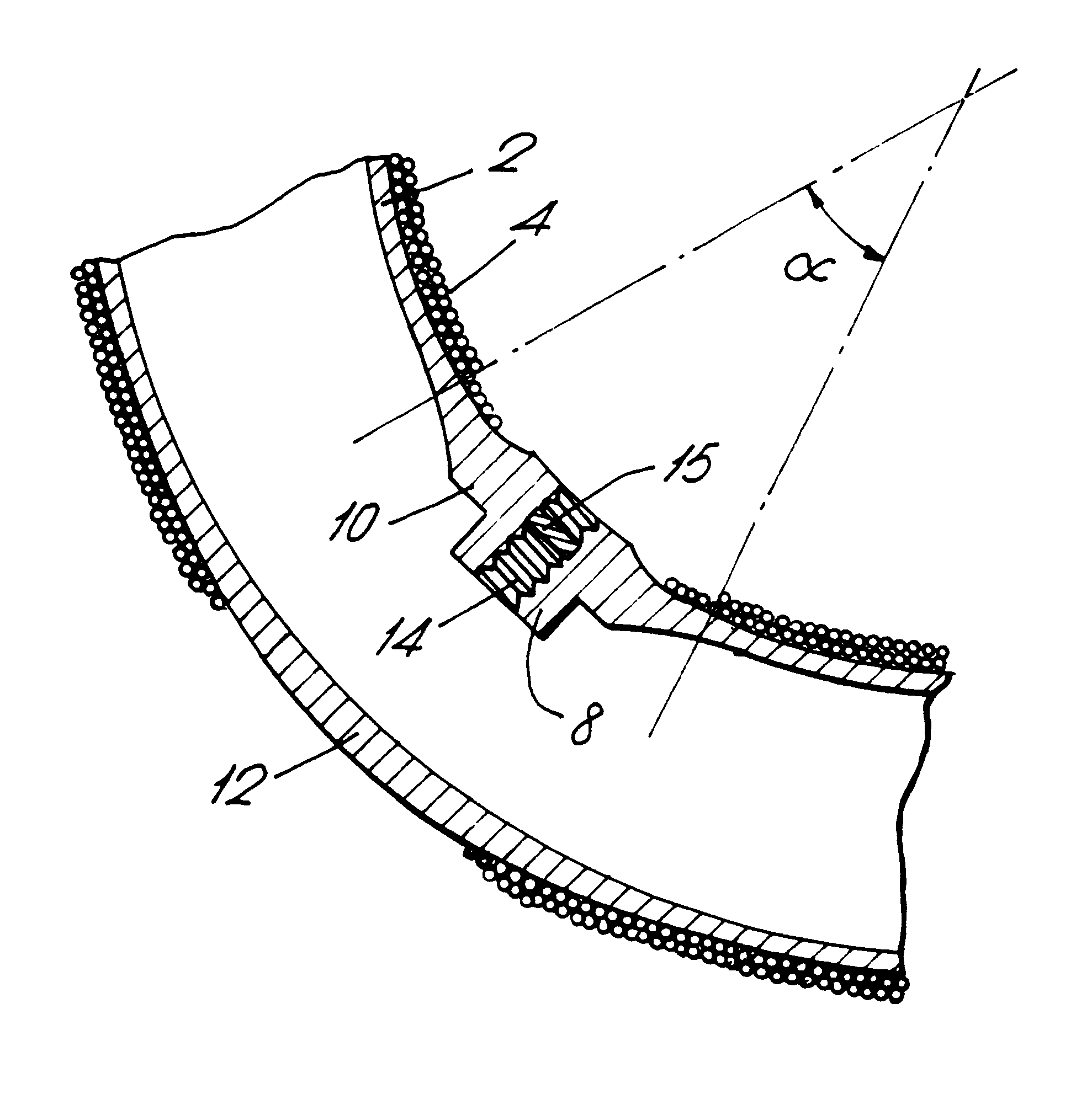
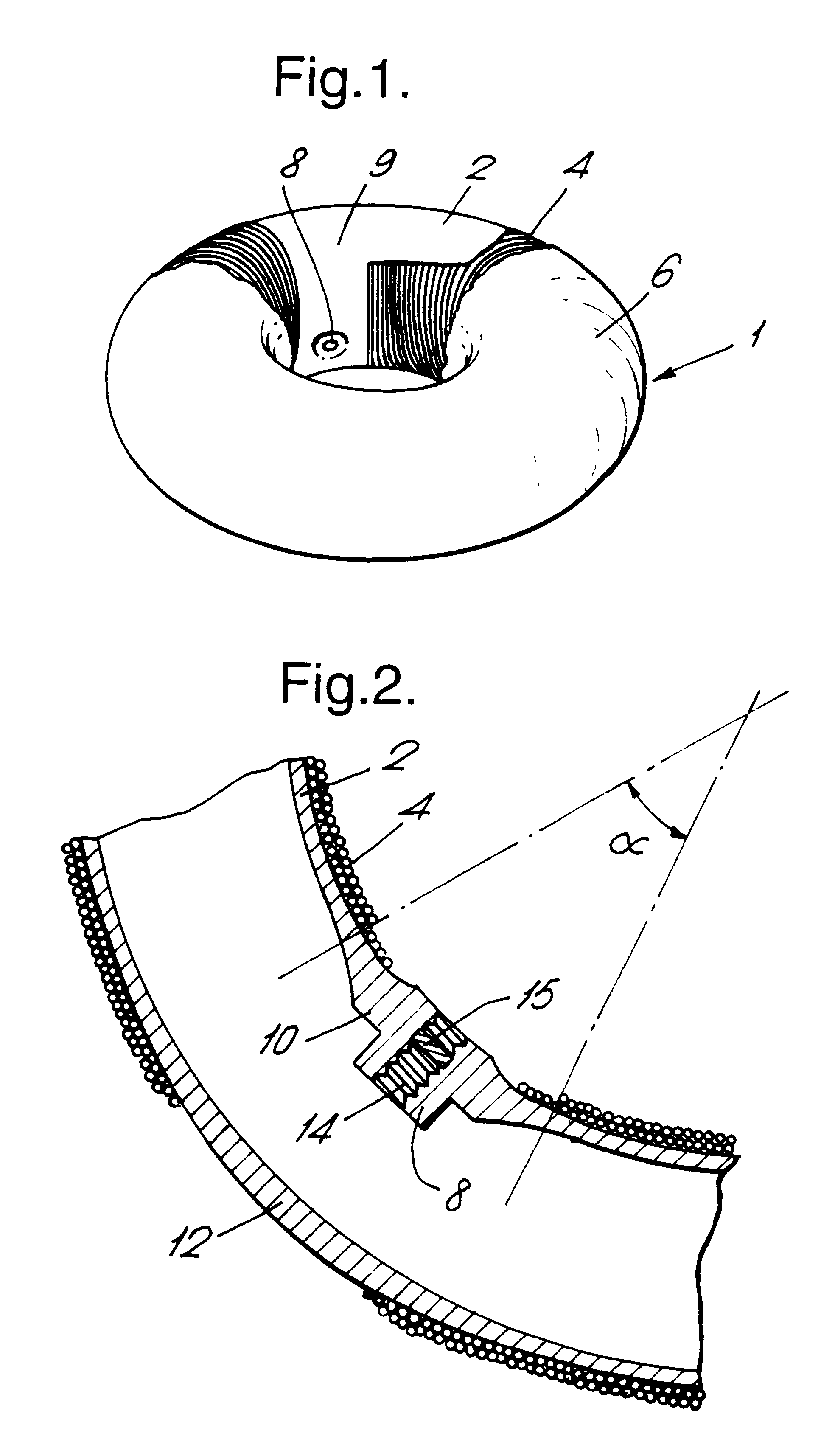
FIG. 1 illustrates a toroidal gas tank for a breathing apparatus according to the invention, provided with detachable supply apparatus and with the apparatus disconnected. A toroidal inner tank 2 having a nine litre capacity and a design pressure of 207 bar (21.1 Mpa) is fabricated from 6061 aluminium alloy, conveniently from two curved "gutters" welded together. The tank 2 is of circular meridianal and transverse section with a total diameter of 400 mm and an inner hole diameter of 128 mm. The tank 2 may, for example, be fabricated from two curved gutters welded together. The wall of the torus has a constant basic wall thickness of 6.5 mm. The tank 2 is overwound with Kevlar-49.TM. fibre 4 to an overwound layer thickness of 2.5 mm measured on the inside of the torus (this will correspond to a lesser thickness on the outside of the torus as a consequence of the build-up effect inherent in the toroidal geometry which was noted above), except for a small section of the casing 9 which ...


PUM

PropertyMeasurementUnit
pressureaaaaaaaaaa
diameteraaaaaaaaaa
diameteraaaaaaaaaa

Abstract

A gas containment and supply apparatus is described consisting of a gas reservoir vessel (1) capable of pressurised gas containment fitted with a gas supply aperture (8) provided with supply means connectable to the gas supply aperture to provide for supply of the gas and control means to control the rate of supply of the gas, in which the gas reservoir is a toroidal pressure vessel comprising a metallic toroidal shell (2) having wound on its surface a tensile load bearing layer of high tensile strength non-metallic fiber (4), the fiber being aligned in a substantially meridional direction on the toroidal shell. Human portable breathing apparatus is described utilising the above.

Description

1. Field of the InventionThe invention relates to a compact gas containment and supply apparatus, particularly one which is readily human portable2. Discussion of Prior ArtTo enhance portability of pressurised gas containment vessels there is a general requirement for high strength combined with relatively low weight. Overwinding around an internal shell is a well established technique both for strength and for weight reduction in the manufacture of cylindrical pressure vessels, such as gun barrels, gas cylinders and the like. Such structures when pressurized are subjected to hoop stresses that are significantly higher than the axial stresses, and the use of an overwinding designed to carry a large part of the hoop load allows the design of the base cylinder to be directed towards meeting only the axial stresses, with a considerable potential for saving in weight. Traditionally such windings were of high tensile strength metal wires. Recent developments in composite material technol...

Claims


Application Information

Patent Timeline
Patent Type & Authority Patents(United States)
IPC IPC(8): A62B9/00F17C1/00F17C1/16A62B7/00F17C1/06F17C1/14
CPCA62B9/00F17C1/16F17C2201/0133F17C2201/058F17C2203/0663F17C2223/036F17C2203/0607F17C2203/0646F17C2205/0338F17C2223/0123F17C2250/0636
Inventor COOK, JOHNRICHARDS, BRIAN J
Owner QINETIQ LTD
Why Eureka
Try Eureka