

Sliding bearing and sliding bearing structure
- Summary
- Abstract
- Description
- Claims
- Application Information
AI Technical Summary
Benefits of technology
Problems solved by technology
Method used
Image

Examples
Embodiment Construction
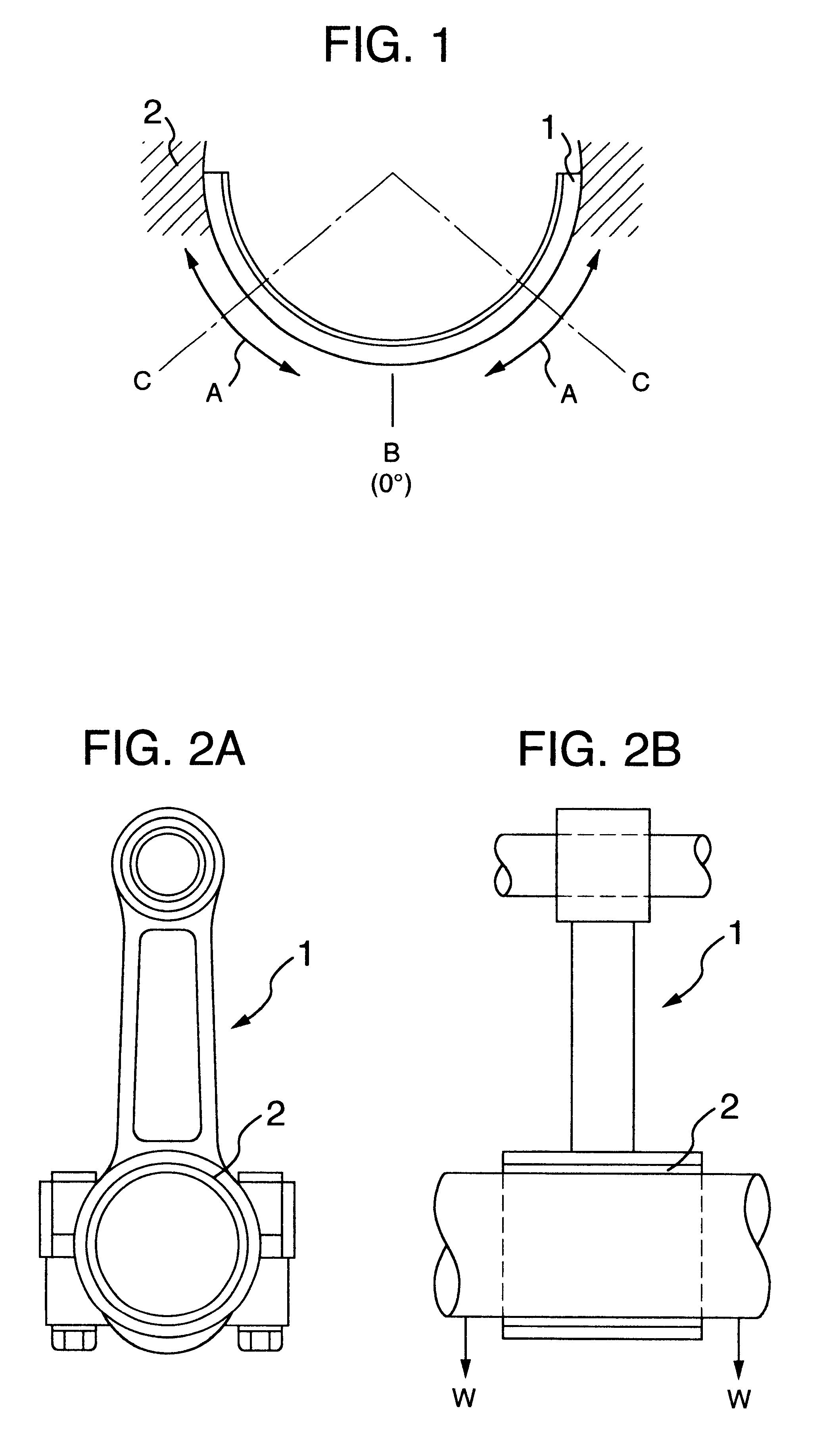
The embodiments of the invention are explained below.
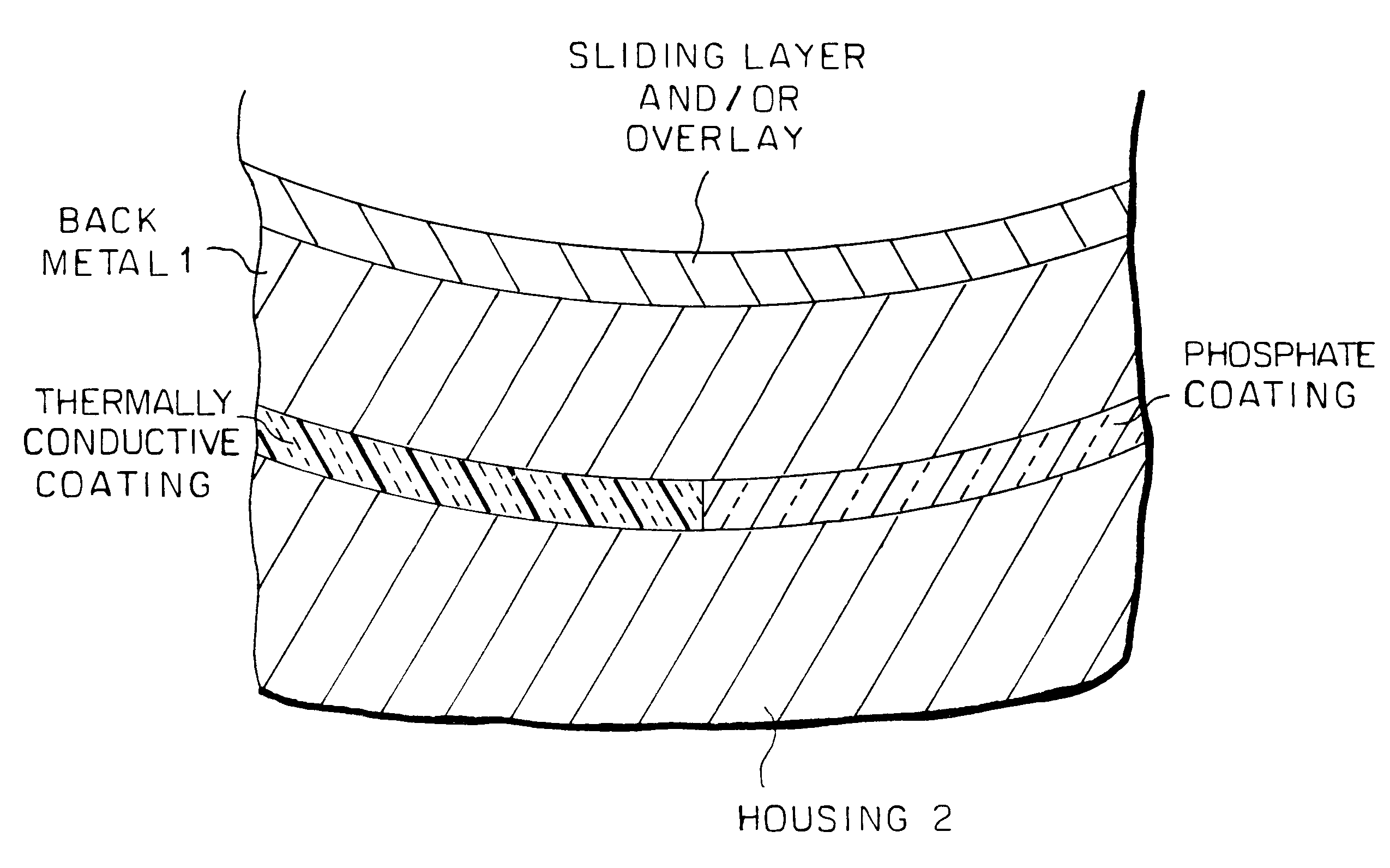
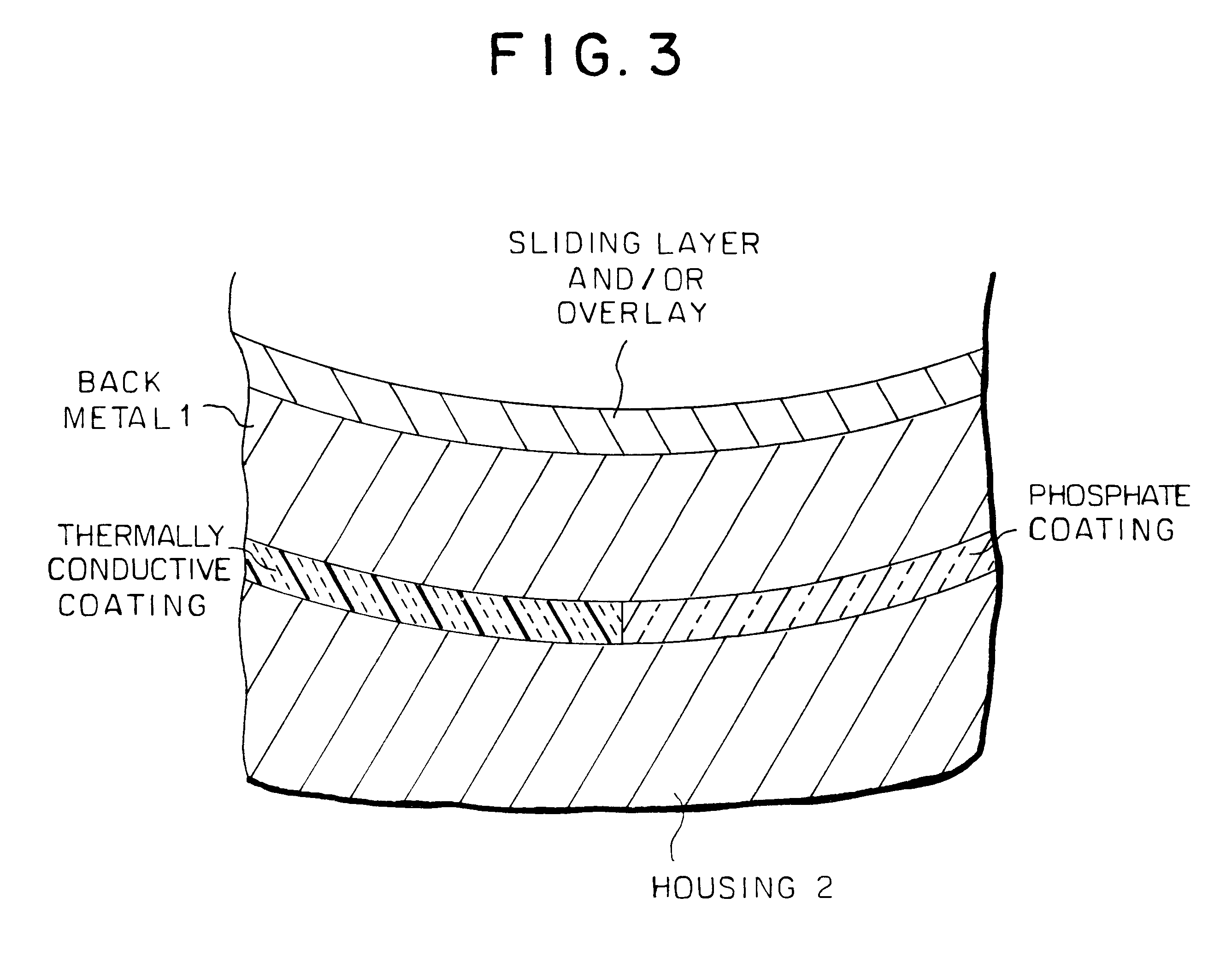
The experiments were performed, as shown in Table 1, regarding each of experimental samples prepared in accordance with embodiments 1 to 10 and comparison examples 1 to 5. As a back metal, a cold-rolled steel sheet (prescribed in JIS G3141SPCC) was used. For example, in the embodiment 1, a half sliding bearing was produced by the steps of: forming a bearing alloy layer of Cu--1.5 wt. %Sn--23 wt. %Pb on this back metal by sintering to thereby obtain a composite sheet, and cutting and shaping this composite sheet into a semicircular shape to thereby obtain the half sliding bearing having an inner diameter of 42 mm, an outer diameter of 45 mm and a width of 17 mm. Further, on the bearing alloy layer, an overlay of Pb--10 wt %Sn--10 wt. %In was formed which had a thickness of 15 .mu.m.
On the other hand, the back face of the back metal of the half sliding bearing was plated with a metal coating of 2 .mu.m in thickness which became a th...
PUM
| Property | Measurement | Unit |
|---|---|---|
| Angle | aaaaa | aaaaa |
| Angle | aaaaa | aaaaa |
| Pressure | aaaaa | aaaaa |
Abstract
Description
Claims
Application Information