Clock synchronization for asynchronous data transmission

a clock synchronization and data transmission technology, applied in the direction of digital transmission, code conversion, pulse technique, etc., can solve the problems of compounded synchronization problems, ineffective traditional synchronization solutions such as phase locked loops, and devices that cannot be assured

Inactive Publication Date: 2002-03-19
NATIONAL INSTRUMENTS
View PDF4 Cites 49 Cited by
  • Summary
  • Abstract
  • Description
  • Claims
  • Application Information

AI Technical Summary

Problems solved by technology

Therefore, if the data stream is simply sampled on edges of the internal clock, the receiving device may not be assured that each time data is sampled, correct data will be received.
This is because even though the frequency of the internal clock may be the same as the data stream transmission rate, the phase between the sampling clock and the data stream may drift so that clock edges of the sampling clock occur during times when data on the data stream is unstable.
However, the problems of synchronization are compounded if no assumptions can be made about the incoming serial data stream.
Traditional synchronization solutions such as a phase locked loops are ineffective for synchronizing to an asynchronous serial digital data stream.
However, an asynchronous digital data stream may not be periodic.
The problem is exacerbated when long strings of zeros or ones are transmitted.
Therefore, a traditional phase locked loop would not be able to maintain synchronization.
Furthermore, conventional phase locked loops may require several clock cycles to synchronize.
Thus, data may be lost for the...

Method used


Image

  • Clock synchronization for asynchronous data transmission
  • Clock synchronization for asynchronous data transmission
  • Clock synchronization for asynchronous data transmission

Examples


Embodiment Construction

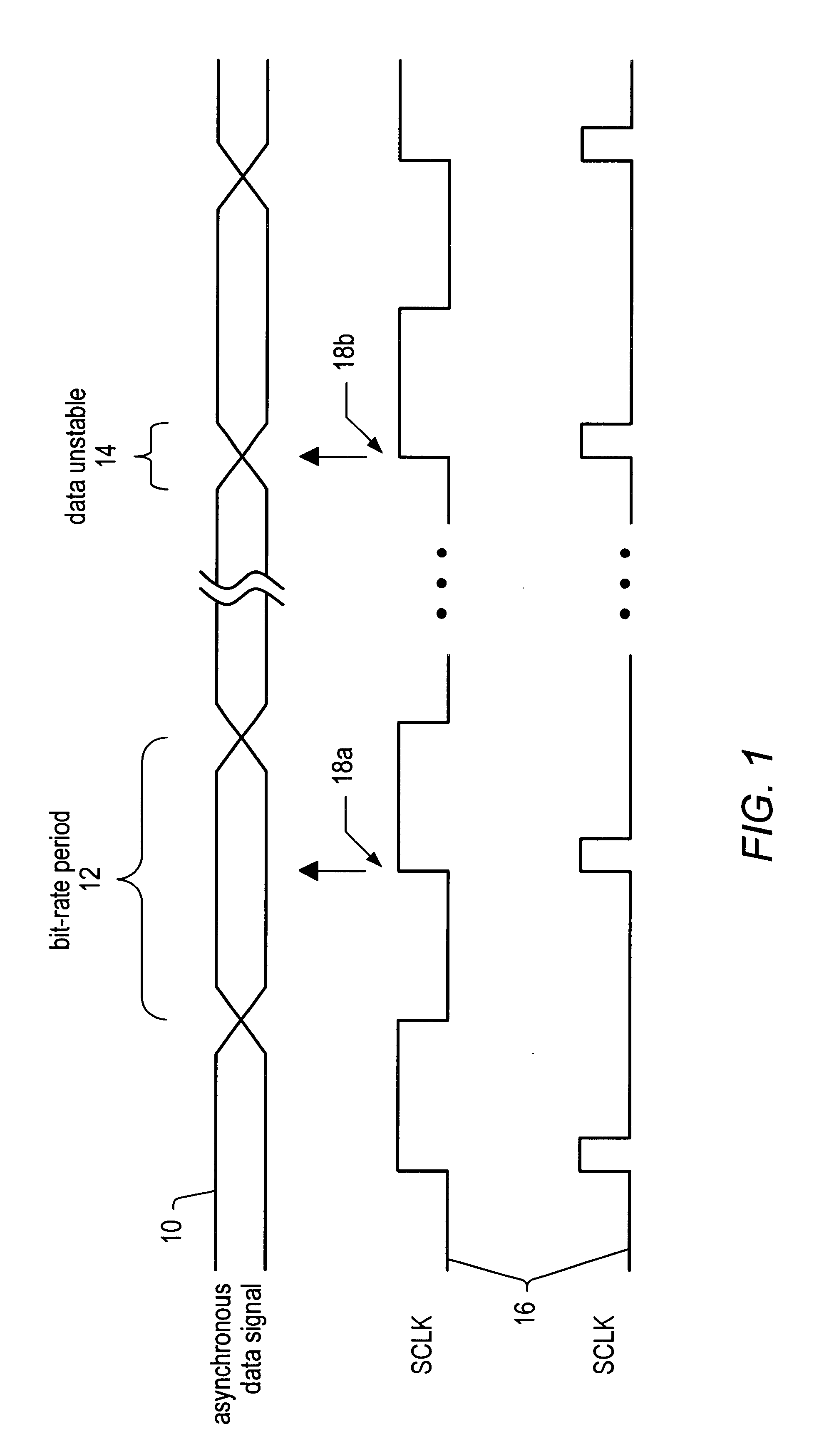
Turning now to the drawings, FIG. 1 illustrates a timing diagram showing an asynchronous data signal 10 and a clock signal 16 for sampling the asynchronous data signal 10. Note that two alternative versions of clock signal 16 are illustrated in FIG. 1. One version shows a clock signal having a symmetrical duty cycle whereas the other version shows a clock signal with an asymmetrical duty cycle. These two versions of the clock signal are illustrated to show that the duty cycle of the sampling clock is not important. Any clock signal providing a periodic edge for sampling may be employed.The clock signal may have a symmetrical duty cycle as illustrated by the first clock signal or the clock signal may comprise periodic sample pulses as shown in the second illustrated clock signal 16.

The asynchronous data signal 10 may be a serial digital data stream having a bit-rate period 12. Bit-rate period 12 corresponds inversely to the frequency at which data is communicated by asynchronous data...


PUM


Abstract

An apparatus for receiving an asynchronous data signal may include a clock generator that generates a clock signal having a frequency approximately equal to the bit rate of the asynchronous data signal. An edge detector may detect transitions of the asynchronous data signal. A dead-band detector may detect when a transition of the clock signal used to sample the data signal occurs within a predetermined amount of time of a transition of the asynchronous data signal so that data sampled on that transition of the clock signal may be invalid. The phase of the clock signal may be adjusted if the transition of the clock signal occurs within this predetermined amount of time. The clock generator may include two programmable counters, one which may be programmed with a bit-rate value so that it generates a signal approximately matching the bit rate of the asynchronous data signal, and the other programmed with a phase-delay value so that it generates a sample clock signal at a phase delay from the signal generated by the first counter. The phase of the sample clock may be adjusted by restarting the counters in response to a transition on the asynchronous data signal. Data may be supplied to a serial-to-parallel converter including a first shift register configured to shift a data word in serially and output the data word in parallel and a second shift register configured to track when the data word had been completely shifted into the first shift register.

Description

The present invention relates to the field of data transmission, and more particularly, to synchronizing to asynchronous data transmissions. One embodiment is related to synchronizing a sampling clock to an asynchronous serial digital data stream.DESCRIPTION OF THE RELATED ARTAsynchronous serial digital transmission is a common form for transferring information in the telecommunication industry. A device that is receiving an asynchronous stream of data must sample the data stream at times when the data is stable in order to guarantee accurate reception of the data stream. A typical receiving device may use an internal sampling clock to sample the serial data stream. However, an asynchronous serial data stream is, by its nature, asynchronous to the internal sampling clock. Therefore, if the data stream is simply sampled on edges of the internal clock, the receiving device may not be assured that each time data is sampled, correct data will be received. This is because even though the...

Claims


Application Information

Patent Timeline
IPC IPC(8): H03L7/00H03M9/00H04L7/00H04L7/033
CPCH03L7/00H04L7/0083H03M9/00H04L7/033
Inventor RYAN, ARTHUR
Owner NATIONAL INSTRUMENTS
Why Eureka
Try Eureka