Brushless motor and its assembly method

a brushless motor and assembly method technology, applied in the direction of instruments, frequency-division multiplexes, packaged goods types, etc., can solve the problems of reduced size and thickness, insufficient buffering capacity, and insufficient rigidity of the elastic body, so as to improve the degree of equipment integration and high density

Inactive Publication Date: 2002-04-02
PANASONIC CORP
View PDF12 Cites 33 Cited by
  • Summary
  • Abstract
  • Description
  • Claims
  • Application Information

AI Technical Summary

Benefits of technology

A first object of the present invention is to meet the above requirements, that is, to contribute to improving the degree of integration of the equipment. Thus, the motor must

Problems solved by technology

In recent years, however, the demand for reduced size and thickness prevents a space for the elastic body from being provided.
Despite its small weight, such metal has a much higher rigidity than resin so its buffering capability is insufficient.
Even enduring a reflow heating temperature (about 250.degree. C.) is difficult.
The inventor attempted to find a conventional technique that meets these requirements, but in vain.
The time required for this operation, however, tends to increase with decreasing size of the motor.
This is because it is more difficult to handle smaller parts.
The electronic

Method used


Image

  • Brushless motor and its assembly method
  • Brushless motor and its assembly method
  • Brushless motor and its assembly method

Examples


embodiment 1

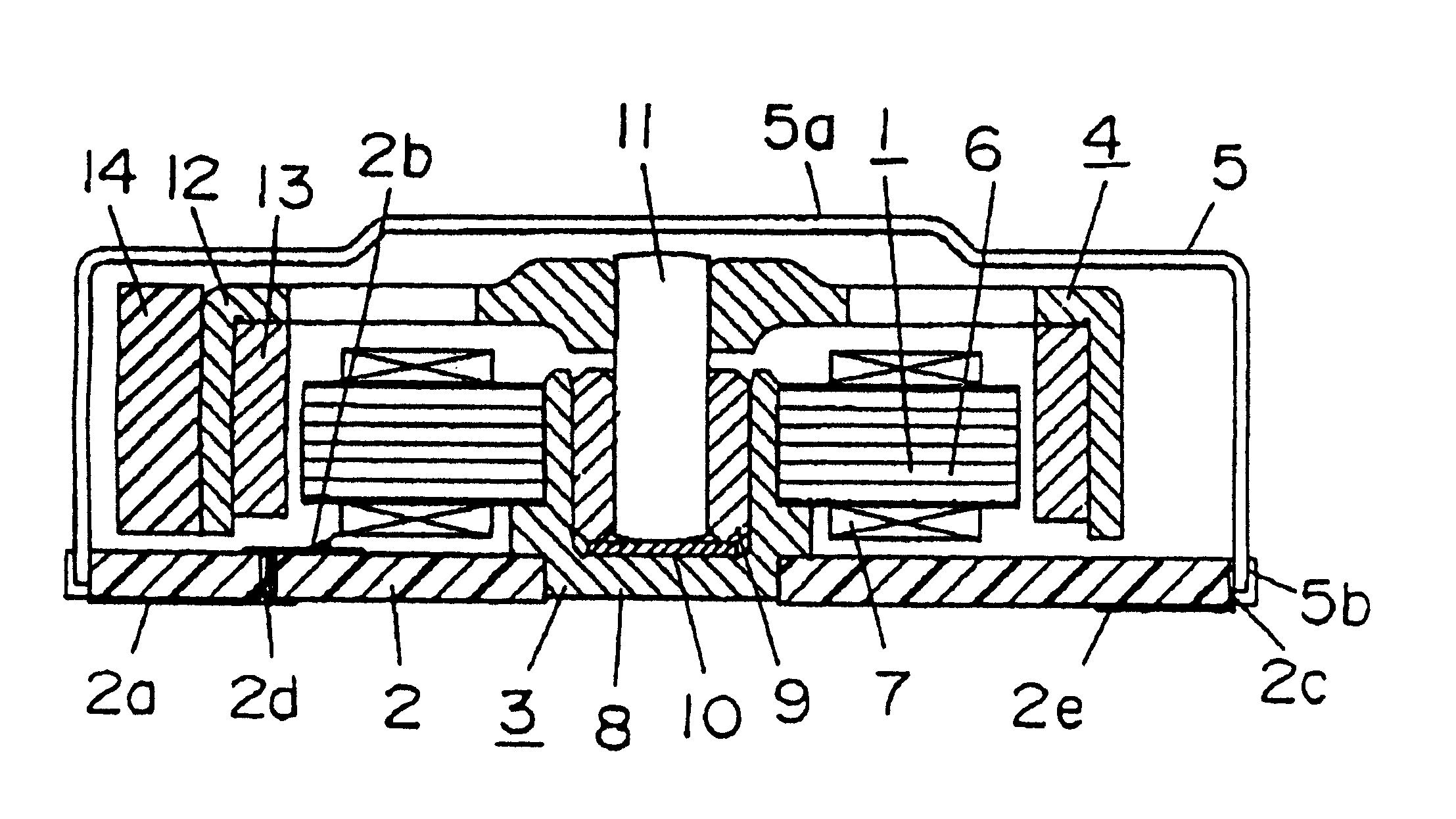
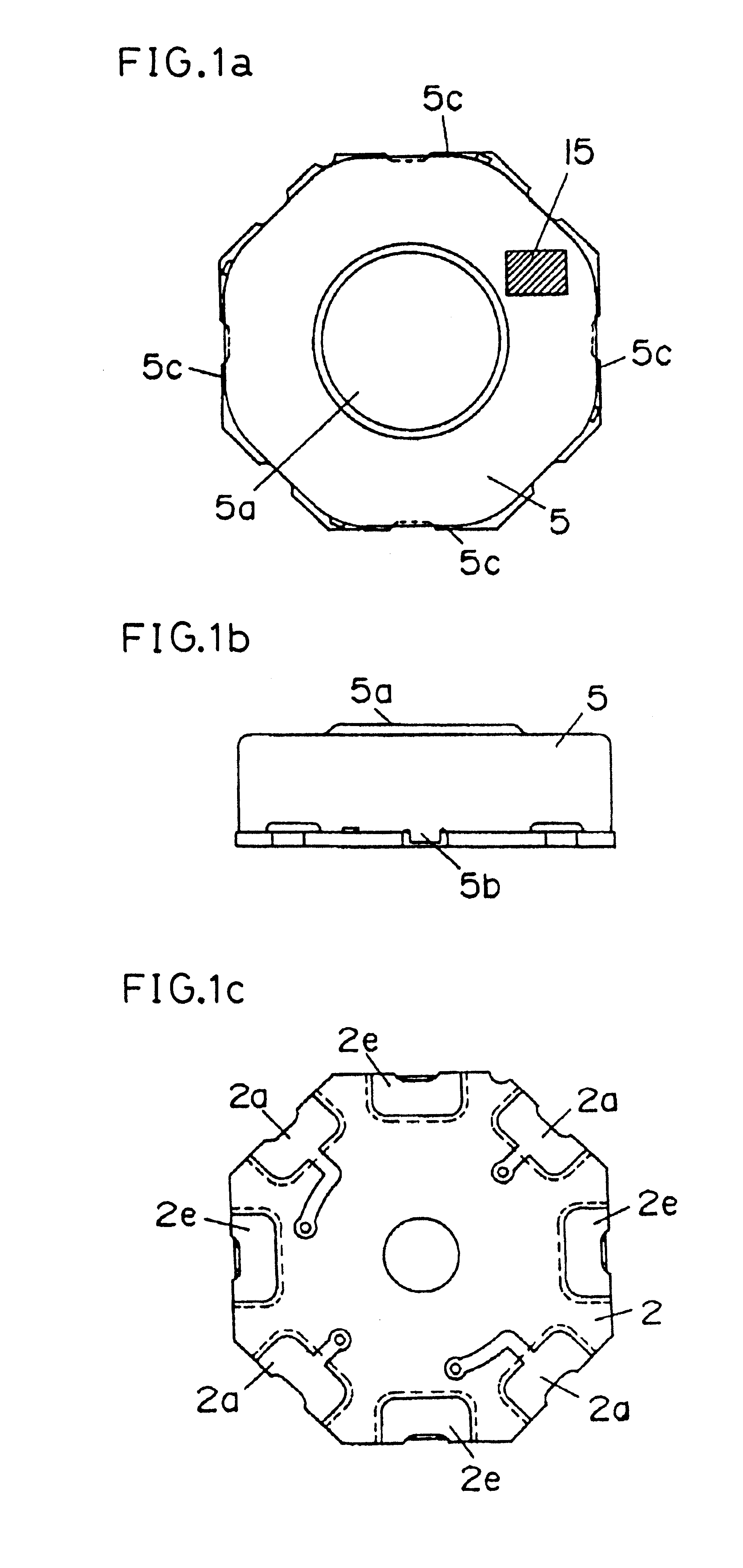
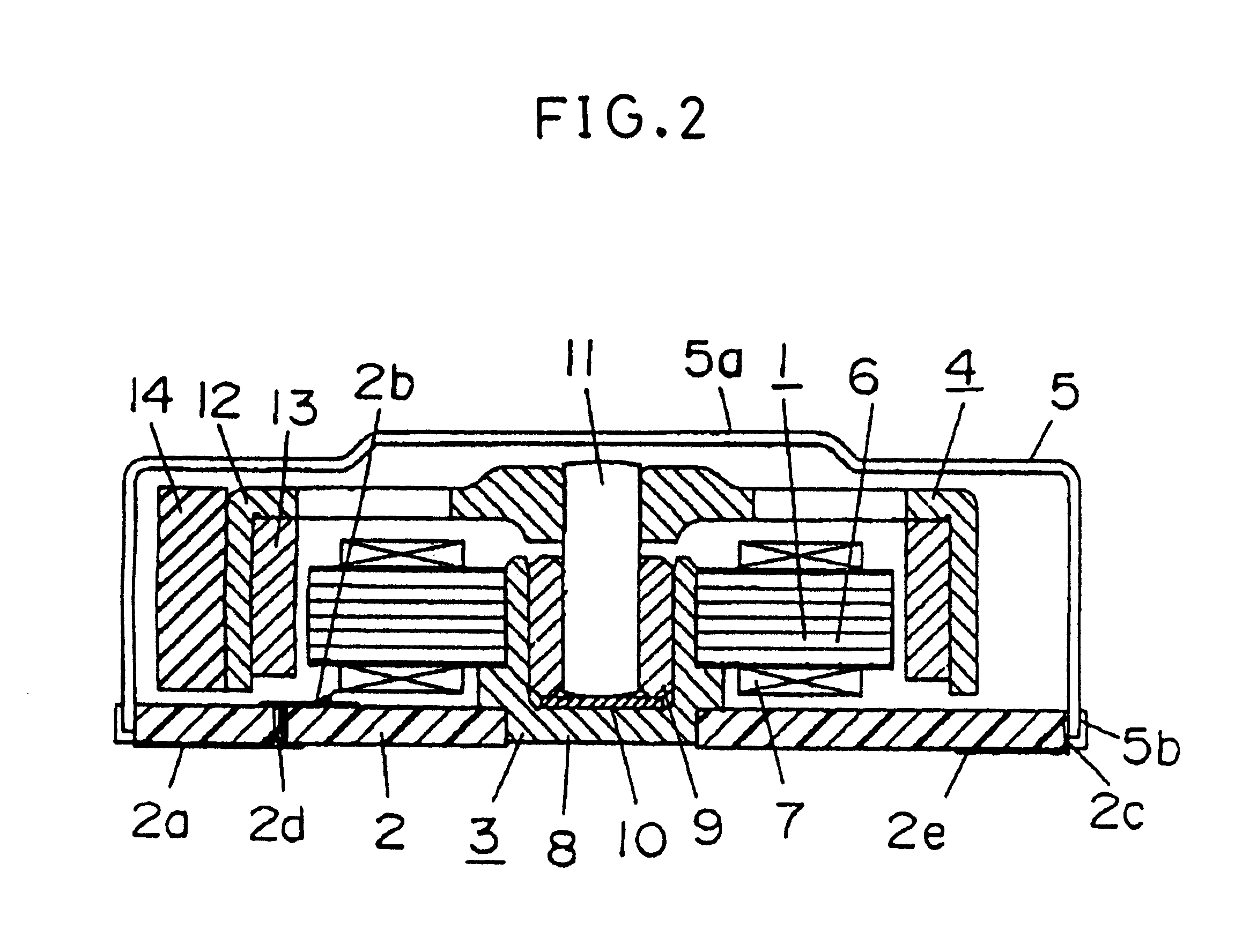
FIG. 1a is a top view of a motor according to Embodiment 1 of the present invention. FIG. 1b is a side view of this motor. FIG. 1c is a bottom view of this motor. FIG. 2 is a structural sectional view of the motor. FIG. 3a is a top view showing a state in which the motor is mounted on a substrate of equipment. FIG. 3b is a side view of this state.

In FIG. 1, a housing of a motor has a flat shape having a top surface, a side, and a bottom surface. The housing appears like an octagon as seen from the top surface. A sucked surface 5a to which a suction chuck can be opposed is located approximately at the center of the top surface. The side is surrounded by eight wall surfaces all over the circumference.

In FIG. 2, the motor comprises a stator 1, a printed circuit board 2, a bearing device 3, a rotor 4, and a cover 5. The cover 5 principally forms the top surface and the side, and the printed circuit board 2 forms part of the side and the bottom surface.

The stator 1 is formed by covering ...

embodiment 2

FIG. 4a is a top view of another motor according to the present invention. FIG. 4b is a side view of this motor. FIG. 4c is a bottom view of this motor.

As shown in the figures, the motor of this embodiment has protruding terminals 25d protruding outward from the side. The protruding terminals 25d are formed by further extending the protruding portion of the cover 25. As shown in FIG. 4c, the eight lands 22a, 22e are located on the bottom surface and the protruding terminals 25d are added to these lands. As is apparent from FIG. 4b, the protruding terminals 25b are approximately flush with the lands 22a, 22e. When placed on the substrate of the equipment and reflow-soldered to it, the motor is fixed by means of the large number of terminals to obtain a higher holding strength.

In addition, although not shown, a structure can be employed in which the protruding terminals alone can provide both a mechanical junction function and an electric connection function. The protruding terminals ...

embodiments 1 and 2

Variation of Embodiments 1 and 2

This section shows a variation of the planar shape. FIG. 5a is a top view of yet another motor that appears like an oval as seen from the top view. FIG. 5b shows a shape similar to that in FIG. 5a. FIG. 5c shows a shape in which two parallel lines are located adjacent to the outer circumference of a circle. FIG. 5d shows a square one as corner of which has been cut. The similar shape in FIG. 5b is obtained by cutting a circle using two parallel lines.

An oval or a similar shape is similar to a circle, so such a motor is characterized in that it can save space and be gripped and in that it has an internal space and is preferred in case of further incorporating electronic parts within the motor. The shape in FIG. 5c is very similar to a circle and saves space, thereby reducing an area of the substrate of the embodiment that is occupied by the motor. The shape in FIG. 5d can also be used as a marking for determining the direction.

FIG. 6a is a top view of ...


PUM


Abstract

Brushless motors for portable information equipment that can be simultaneously reflow-soldered to a substrate and efficiently and densely mounted thereon in such a way that the coupled portion between the motor and the substrate has a high impact resistance, thereby providing small and reliable portable information equipment having a high productivity. The brushless motor including a housing having a bottom surface, a side surface, and a top surface, the bottom surface being located adjacent and opposite to a substrate of equipment; a plurality of lands (2a, 2e) on the bottom surface that can be mechanically or electrically joined with the substrate of the equipment; a stator (1), a bearing device (3), and a rotor (4) inside said housing, the stator (1) having a stator core (6) and a coil (7) wound around the stator core (6), the rotor (4) having a magnet (13) and being supported by the bearing device (3) so as to rotatably surround the periphery of the stator (1), the rotor (4) further including a circular weight (14).

Description

The present invention relates to the structure of a small flat brushless motor and its assembly method.Portable information equipment (hereafter referred to as "equipment") including, for example, cellular telephones are desired to be smaller, lighter, and thinner, to give a sophisticated impression, and to endure longtime use. Equipment manufacturers are making various efforts to meet these demands. They are attempting to reduce the size and power consumption of electronic parts integrated into the equipment, to use multilayer wiring substrates to allow electronic parts to be densely integrated while increasing productivity, and to configure enclosures using light metal such as magnesium to reduce the thickness of the equipment and give it a sophisticated impression. There are similar demands on flat brushless motors used as a drive source for the equipment.A vibration generating function for silent calls is now essential for cellular telephones. The vibration generating function i...

Claims


Application Information

Patent Timeline
IPC IPC(8): H02K7/06B65D85/38H02K5/00
CPCH02K5/00H02K7/063H02K5/225H02K2211/03
Inventor FUKUDA, YOSHIAKIKUYAMA, KOJIUEHARA, TOSHIOITAKURA, KAZUHITOYAMAMOTO, CHIAKIYOSHIDA, SHIGERUFUJINAKA, HIROYASUUMEHARA, MIKIOSATO, NORIYOSHI
Owner PANASONIC CORP
Why Eureka
Try Eureka