Aerodynamic component with a leading edge flap

a leading edge and component technology, applied in the direction of aircraft power plants, transportation and packaging, aircraft, etc., can solve the problems of unoptimized aerodynamics in certain sections or areas, unoptimized is the possibility of dynamic stall, and the design and construction of the rotor blade of the helicopter requires numerous compromises, etc., to achieve easy exchangeability of the nose flap, high adjustment speed, and structural simplicity

Inactive Publication Date: 2002-04-16
EADS DEUT GMBH
View PDF7 Cites 38 Cited by
  • Summary
  • Abstract
  • Description
  • Claims
  • Application Information

AI Technical Summary

Benefits of technology

The nose flap is preferably so-constructed that it forms the leading edge of the blade including its flow profile along the entire length of the noseflap. Such a structure does not differ aerodynamically in its profile in the neutral position of the nose flap from a conventional flow profile constructed for the same purpose. There may be situations, such as structural conditions, making it necessary to journal the nose flap outside of the respective blade section contour or profile. However, the integration of the nose flap into the blade section provides an aerodynamically more advantageous profile or contour when the nose flap is in its neutral position and when it is in its deflected position. Another advantage of integrating the nose flap into the contour or profile of the blade is seen in that...

Problems solved by technology

As a result, the design and construction of a helicopter rotor blade requires numerous compromises due to the non-stationary events that occur during flight of a helicopter.
Thus, it is in the nature of a helicopter blade that its aerodynamics are not optimal in certain sections or areas along the blade if the rotor blade construction is fixed.
For example, one aspect that is not optimal is the possible dynamic stall when the rotor blade is rotated in the reverse direction.
However, at a certain point such steep angling leads to dynamic stall along locally limited areas of the rotor blade.
On the one hand, the dynamic stall may cause strong vibrations.
On the other hand, the dynamic stall limits the performance of the helicopter.
Moreover, the flight comfort is noticeably reduced for the pilot and the passengers by the noise caused by the blades and by the vibrations in the passenger cell.
Moreover, such vibrations lead to a premature tiring of people and to fatigue failures in the materials of which the helicopter components are made.
As a result, an incre...

Method used


Image

  • Aerodynamic component with a leading edge flap
  • Aerodynamic component with a leading edge flap
  • Aerodynamic component with a leading edge flap

Examples


Embodiment Construction

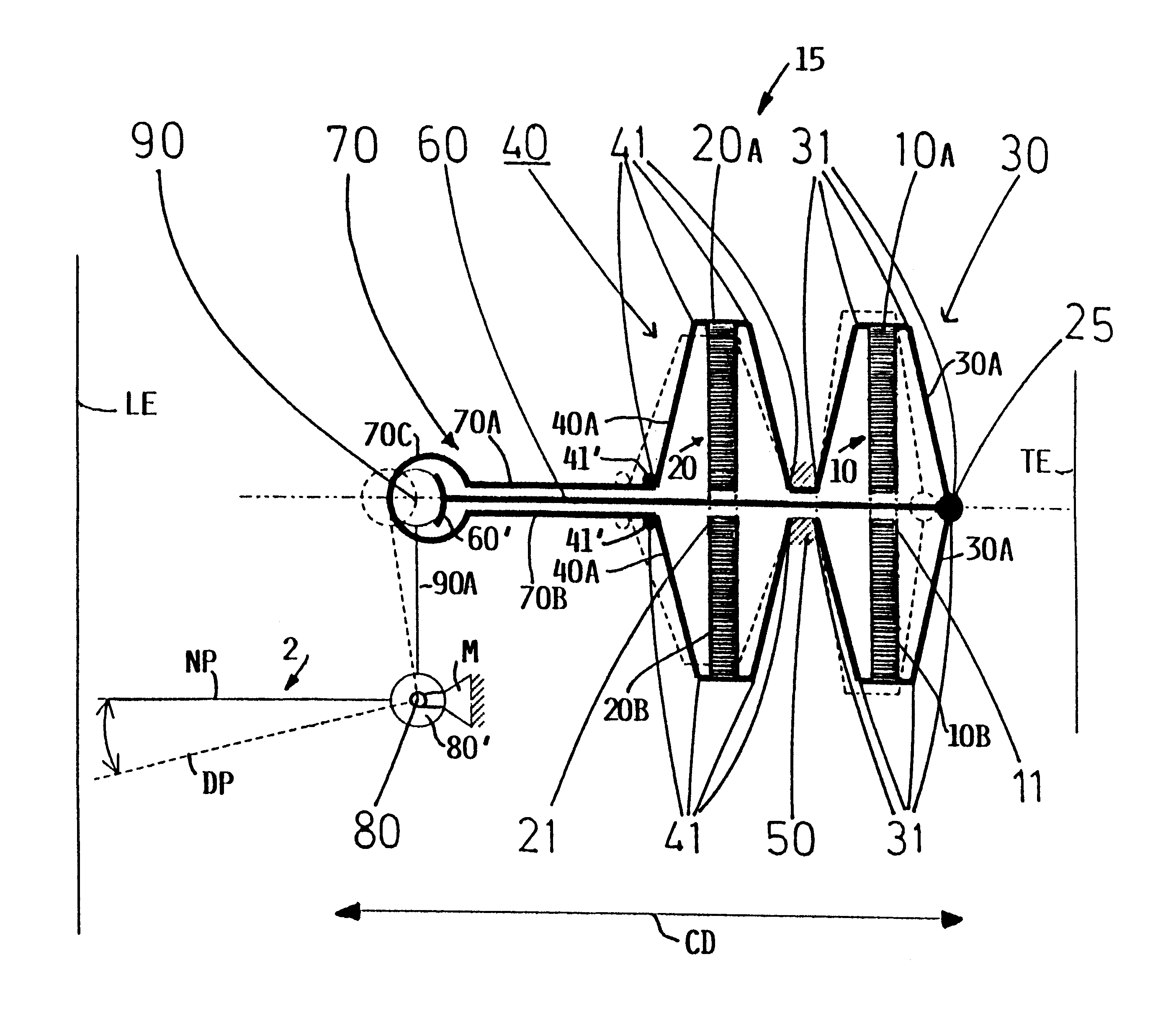
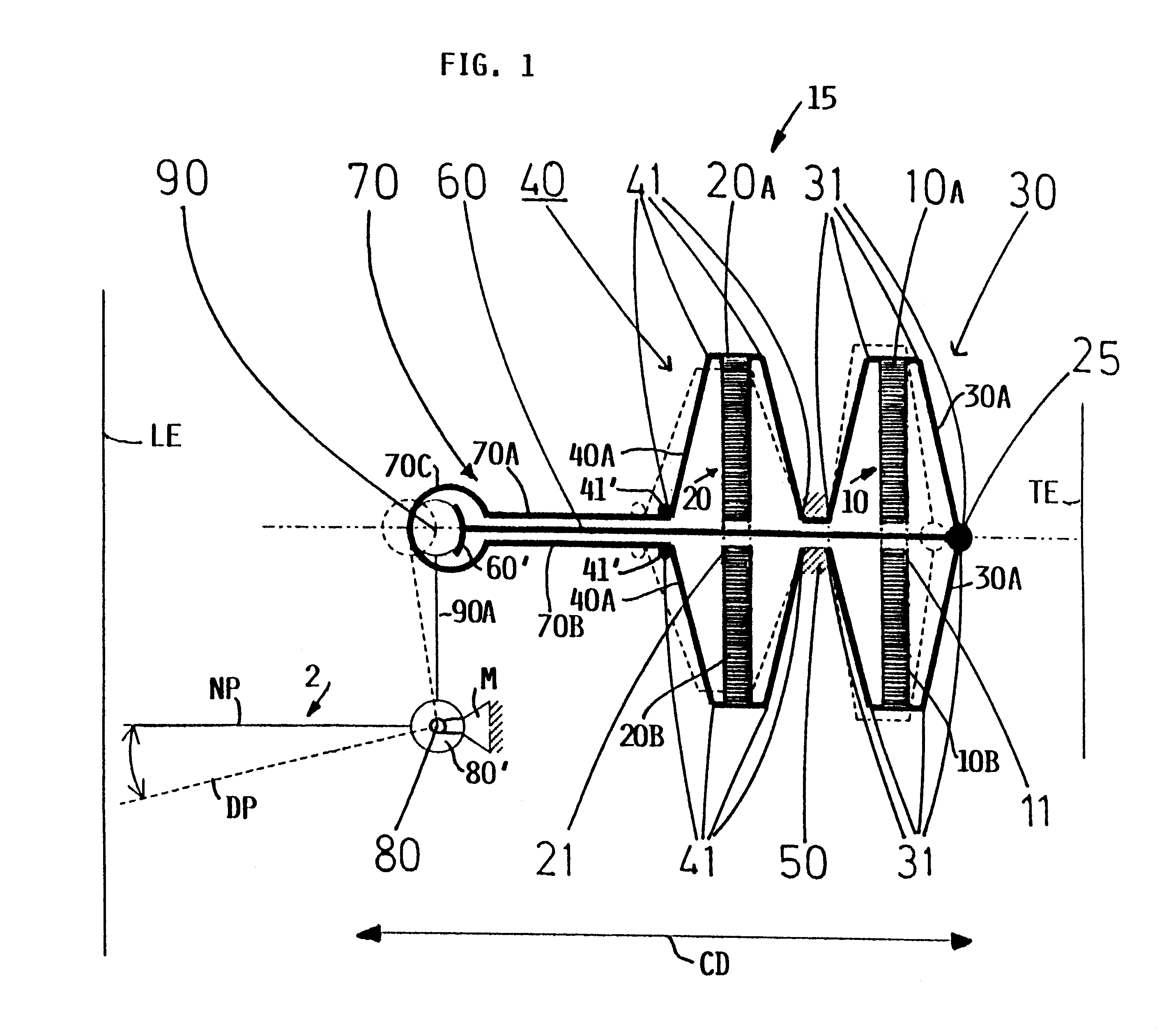
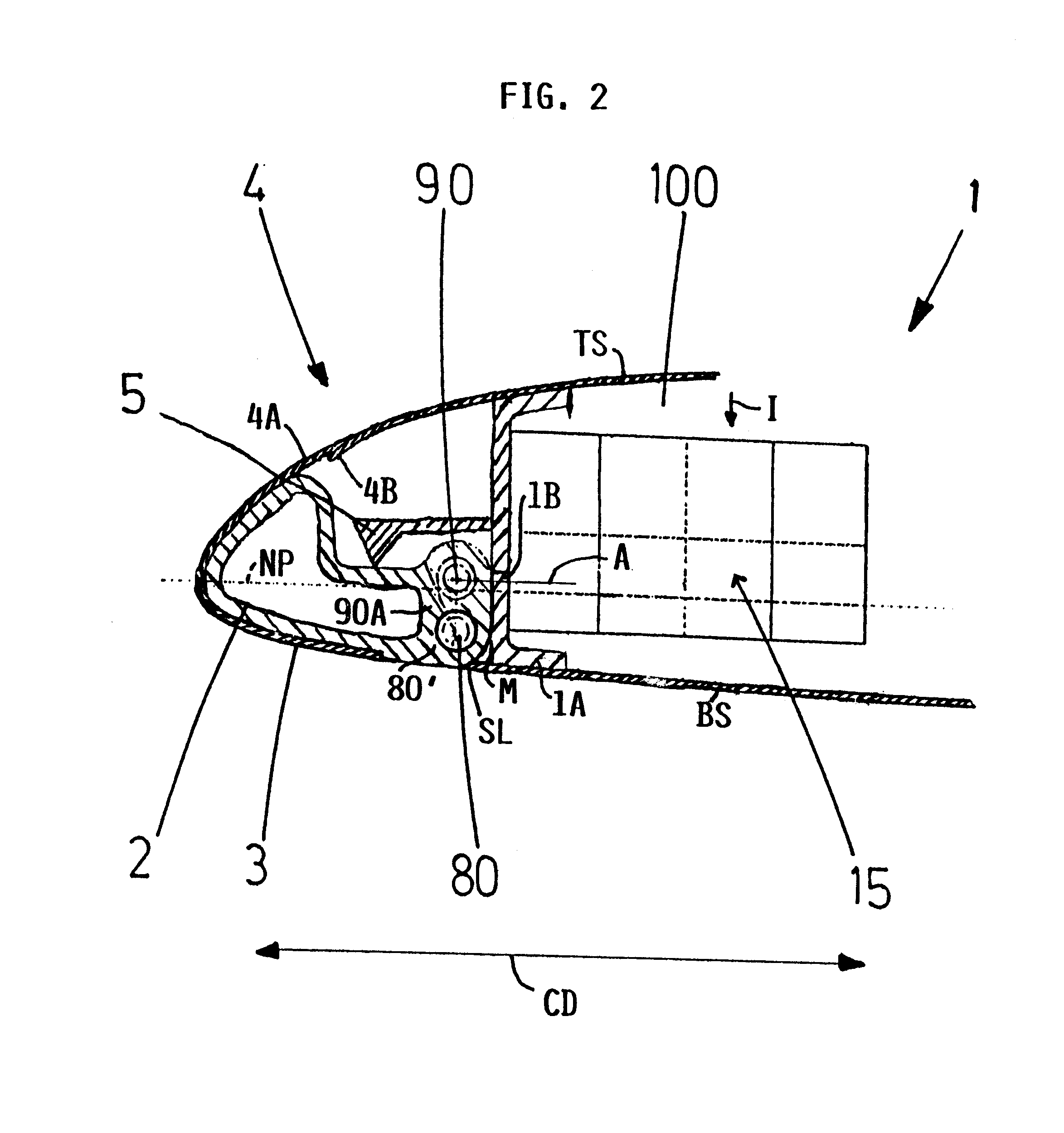
The sectional view of FIG. 1 shows schematically the present piezo-drive 15 with piezo-drive elements 10 and 20 extending longitudinally of an aerodynamic component not shown. The chord plane of the aerodynamic component extends perpendicularly to the drawing sheet and to the sectional plane. The aerodynamic component is, for example a helicopter rotor blade 1 shown in FIGS. 2 and 3. A leading edge or nose flap 2 is shown in FIG. 1 only as a horizontal line NP representing the neutral position of the nose flap 2.

The first piezo-element 10 is positioned closer to a trailing edge TE while the second piezo-element 20 is positioned between the first element and the leading edge LE. Thus, the two piezo-drive elements 10 and 20 forming a pair are oriented according to the invention in the chord direction of the aerodynamic component such as a helicopter rotor blade 1 shown in FIG. 2. In FIG. 1, the blade length direction extends perpendicularly to the chord direction CD. Thus, the element...


PUM


Abstract

An aerodynamic component such as a helicopter rotor blade has an aerodynamic flow profile, a free end and a mounting end forming a blade root for attachment to a rotor mast. A blade section between the root and the free end has a leading edge and a trailing edge as viewed in the flow or chord direction. The blade is enclosed on its suction side and its pressure side with a respective skin. A nose flap or leading edge flap is secured to the leading edge by a bearing or hinge. The blade tilting angle is adjustable by piezo-drive elements arranged in at least one pair forming an actuator for each nose flap. The piezo-elements of a pair are arranged in the chord direction one behind the other and the pair is secured to the body of the blade by a fixed point positioned between the elements of a pair. The expansion and contraction from the piezo-element closer to the trailing edge is transmitted to the flap by a push rod. The expansion and contraction of the piezo-element closer to the leading edge is transmitted to the flap by a pronged pull-fork. The push rod and the pull-fork drive a free end of a lever secured to the flap, whereby a displacement of the push rod or of the pull fork causes the tilting adjustment of the flap by a push-pull action.

Description

PRIORITY CLAIMThis application is based on and claims the priority under 35 U.S.C. .sctn.119 of German Patent Application 200 04 499.0, filed on Mar. 14, 2000, the entire disclosure of which is incorporated herein by reference.The invention relates to aerodynamic components in general and particularly to helicopter rotor blades having a leading edge flap that is driven by a piezoelectric actuator.BACKGROUND INFORMATIONIn rigid wing aircraft, three spatially separated systems are conventionally used to control the lift, the propulsion, and the steering. Contrary thereto, in a helicopter the main rotor substantially assumes itself the above-mentioned control functions to assure a controlled flight. As a result, the design and construction of a helicopter rotor blade requires numerous compromises due to the non-stationary events that occur during flight of a helicopter. Thus, it is in the nature of a helicopter blade that its aerodynamics are not optimal in certain sections or areas al...

Claims


Application Information

Patent Timeline
IPC IPC(8): B64C27/615B64C27/00
CPCB64C27/001B64C27/615Y02T50/34B64C2027/7283Y02T50/30
Inventor LORKOWSKI, THOMASHERMLE, FRANKJAENKER, PETER
Owner EADS DEUT GMBH
Why Eureka
Try Eureka