Guide device for production risers for petroleum production with a "dry tree semisubmersible" at large sea depths

a technology of production risers and guide devices, which is applied in the direction of route marking with anchored lightships, floating buildings, bulkheads/piles, etc., can solve the problems of higher lifting and assembly costs, higher weight and price of heavier dimensioned steel plates, and increased drilling and dimensioning

Inactive Publication Date: 2002-04-23
PGS OFFSHORE TECH
View PDF28 Cites 69 Cited by
  • Summary
  • Abstract
  • Description
  • Claims
  • Application Information

AI Technical Summary

Benefits of technology

One main buoyancy member is arranged for being held on the riser preferably in level with, and guided by the lateral stabilization devices arranged in the lower guide plate, below the upper, more wave- and current-influ

Problems solved by technology

Such a design has economic disadvantages in that the deep draught requires heavier plate dimensioning to resist the higher water pressure.
Heavier dimensioned steel plates entails higher weight and price.
The deep draught of the assembled operative platform requires assembly at deep draught in deep water near the field, meaning higher lifting and assembly costs.
a) At the large depths which may be in question: more than 1200-1600 meters, the seabed sediments may consist of less compacted unconsolidated organic mud, fine silt and clay particles with low density, low shear resistance and high water content, as distinct from glacially worked compacted clay/sand-containing sediments which constitute an essential part of the sea bed in the North Sea and the Norwegian Sea.
b) The sea bed can contain petroleum fractions forming so-called "hydrates" being kept in a partial frozen phase at shallow depths below the sea bed and is presumed to be deposited from escaping petroleum fluids from deeper geological laye

Method used


Image

  • Guide device for production risers for petroleum production with a "dry tree semisubmersible" at large sea depths
  • Guide device for production risers for petroleum production with a "dry tree semisubmersible" at large sea depths
  • Guide device for production risers for petroleum production with a "dry tree semisubmersible" at large sea depths

Examples


Embodiment Construction

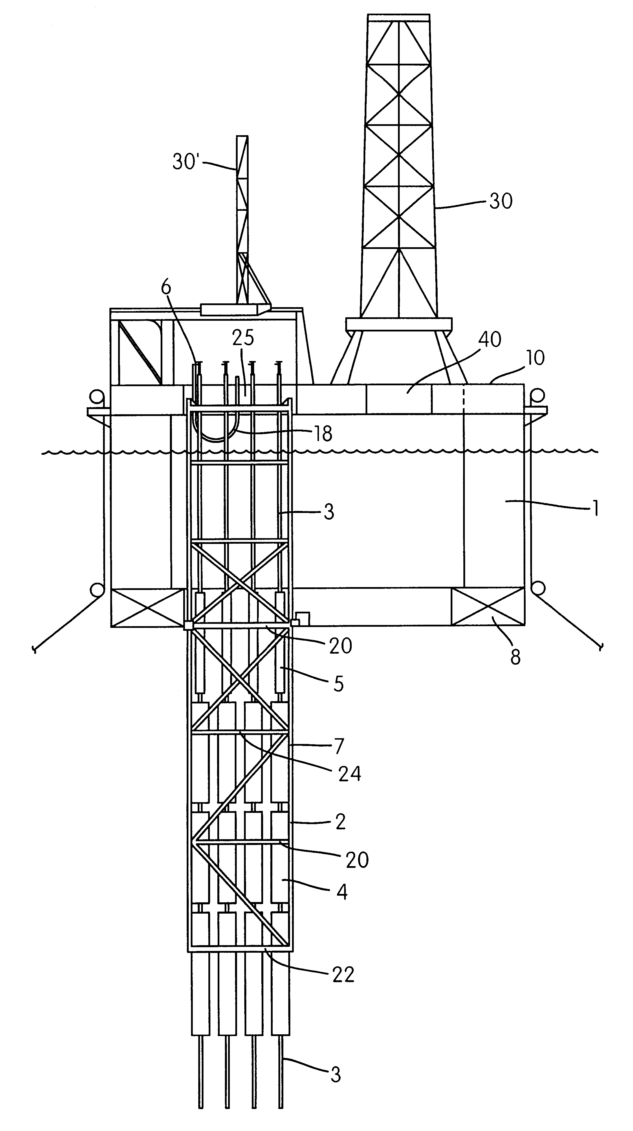
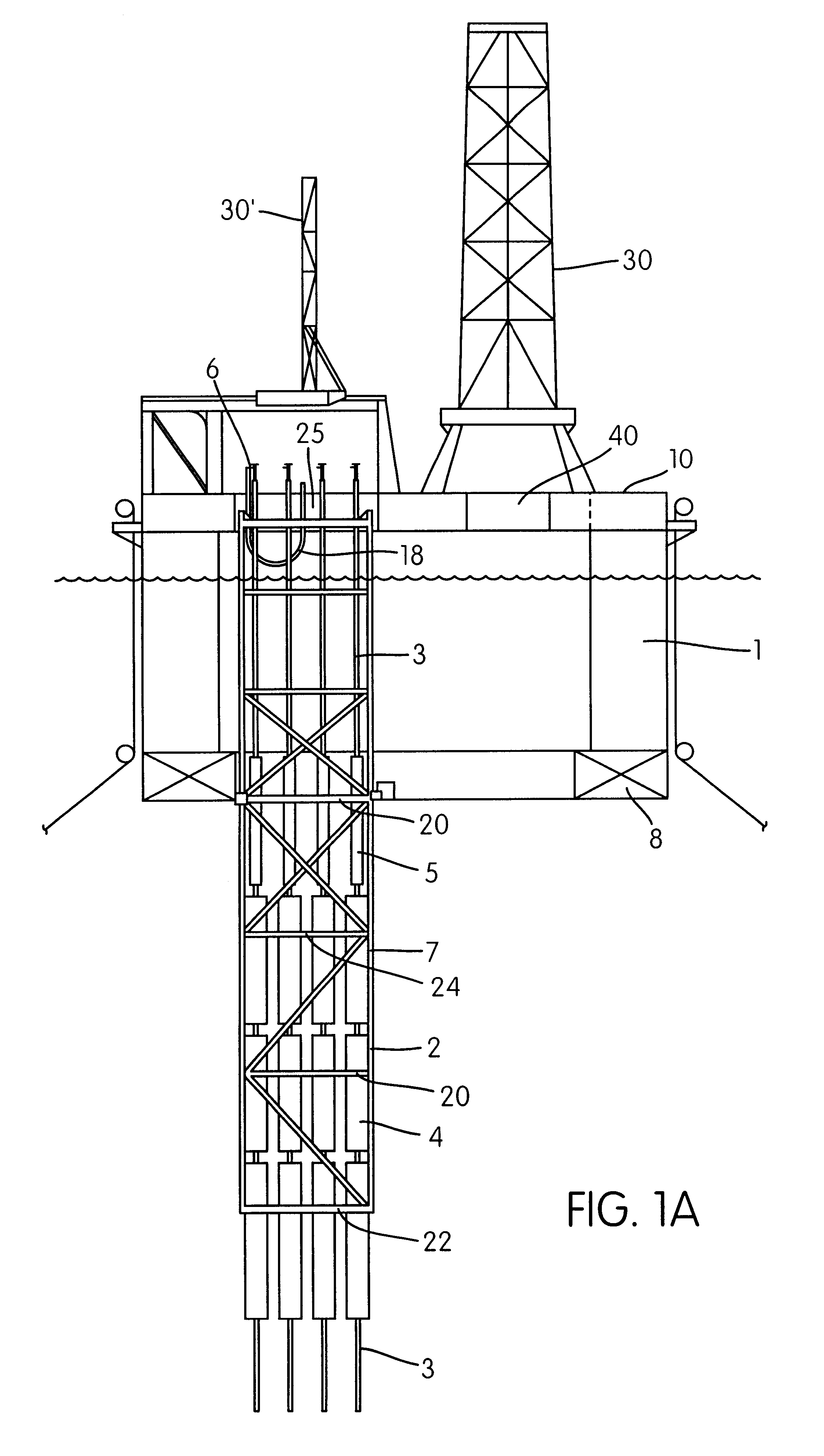
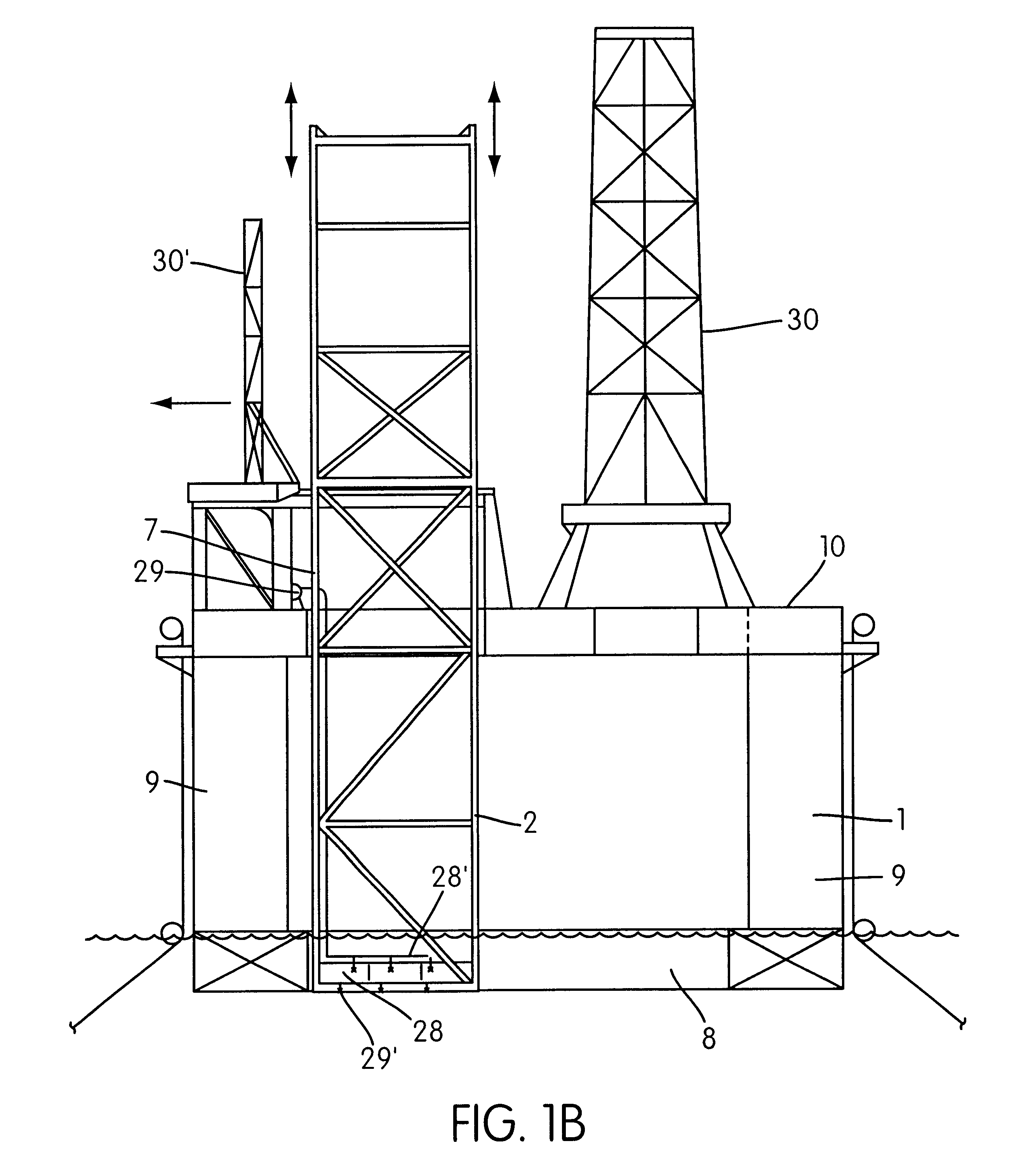
FIG. 1a shows a vertical section of a system according to the invention, comprising a semisubmersible platform or vessel 1 with one or more pontoons 8. In a preferred embodiment, the vessel includes a ring pontoon 8, shown in partial vertical section with a guide frame 2 for one or more riser pipes 3. The guide frame 2 is shown arranged in a lower or "submerged" operational position, with the upper part of the guide frame 2 being arranged near the level of the main or weather deck 10 of the platform. In the lower operational position, the frame 2 extends through the splash zone and down through the most strongly influenced wave- and current-influenced zone, to a depth below the pontoon 8.

The guide frame 2 surrounds and guides one or more risers 3 and one or more main buoyancy members 4 and, in a preferred embodiment, auxiliary buoyancy members 5 arranged to carry the weight of the riser 3. The buoyancy members 4,5 are arranged separately on each riser. In a preferred embodiment of t...


PUM


Abstract

A system for use in petroleum production at sea includes a guide frame for one or more riser pipes, on a semisubmersible production vessel. One or more main buoyancy member are arranged separately on at least one riser to carry the main part of the riser's weight. Each riser separately carries a Christmas tree on its top, near a main deck of the vessel. The guide frame comprises vertical main elements extending vertically downwards from the deck, through the splash zone and through the upper, more wave- and current-influenced zone of the sea. The guide frame also includes horizontal guide plates comprising vertically open cells formed of a horizontally arranged framework of beams. Lateral stabilization devices guide the risers' and the main buoyancy members' vertical movement relative to the vessel and restrict horizontal movement of the risers with respect to the guide frame. The guide plates are arranged in at least two levels on the guide frame. A lower guide plate is arranged at the lower ends of the vertical main elements', and a guide plate is arranged just below or near the splash zone. At least one main buoyancy member is held on the riser in level with, and guided by, lateral stabilization devices arranged in one or more guide plates below the upper, more wave- and current-influenced zone near the sea surface. The risers are without buoyancy elements through the splash zone, and thus are less exposed to the water forces in the upper zone of the sea.

Description

This application claims priority to Norwegian patent application Ser. No. 1999.1470, filed Mar. 25, 1999 and Norwegian patent application Ser. No. 2000.0831, filed Feb. 18, 2000. This application concerns a frame for stabilizing risers on a petroleum production vessel, preferably for production risers with "dry" wellheads, i.e. with Christmas trees arranged on the deck of a freely floating platform. The petroleum production considered takes place at very large sea depths, very likely more than 1200-1600 meters.APPROACH TO THE PROBLEMThe invention is in one embodiment adapted for use in sea areas with the estimated wave height H.sub.max being in the order of amplitudes between 5 and 10 m, thus considerably less than the H.sub.max in the order of 25-30 m required for areas in the North Sea, conditions requiring considerably larger dimensioned and consequently heavier, more expensive vessels. A considerable problem in petroleum production at sea is to guide risers through the splash zo...

Claims


Application Information

Patent Timeline
IPC IPC(8): E21B19/00
CPCE21B19/004B63B35/4413B63B1/107
Inventor B.O SLASHED.RSETH, KNUTOFTEN, OLA
Owner PGS OFFSHORE TECH
Why Eureka
Try Eureka