

Gas turbine, combined cycle plant and compressor
a combined cycle plant and compressor technology, applied in the field of gas turbines, can solve the problems of complex compressor configuration, increased scale as a whole, and inability to achieve power augmentation and thermal efficiency augmentation, so as to achieve the effect of augmentation of power output and thermal efficiency
- Summary
- Abstract
- Description
- Claims
- Application Information
AI Technical Summary
Benefits of technology
Problems solved by technology
Method used
Image

Examples
first embodiment
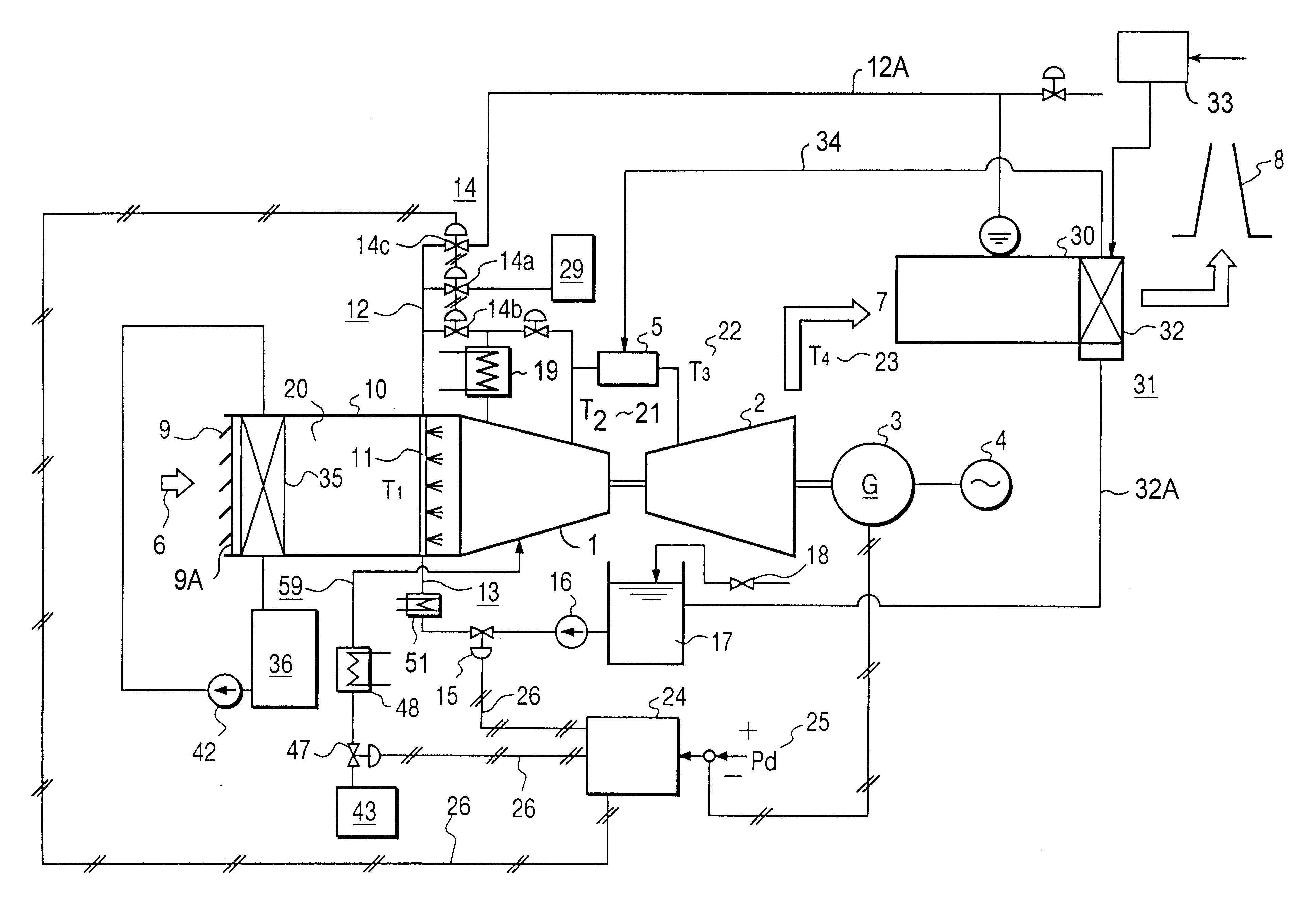
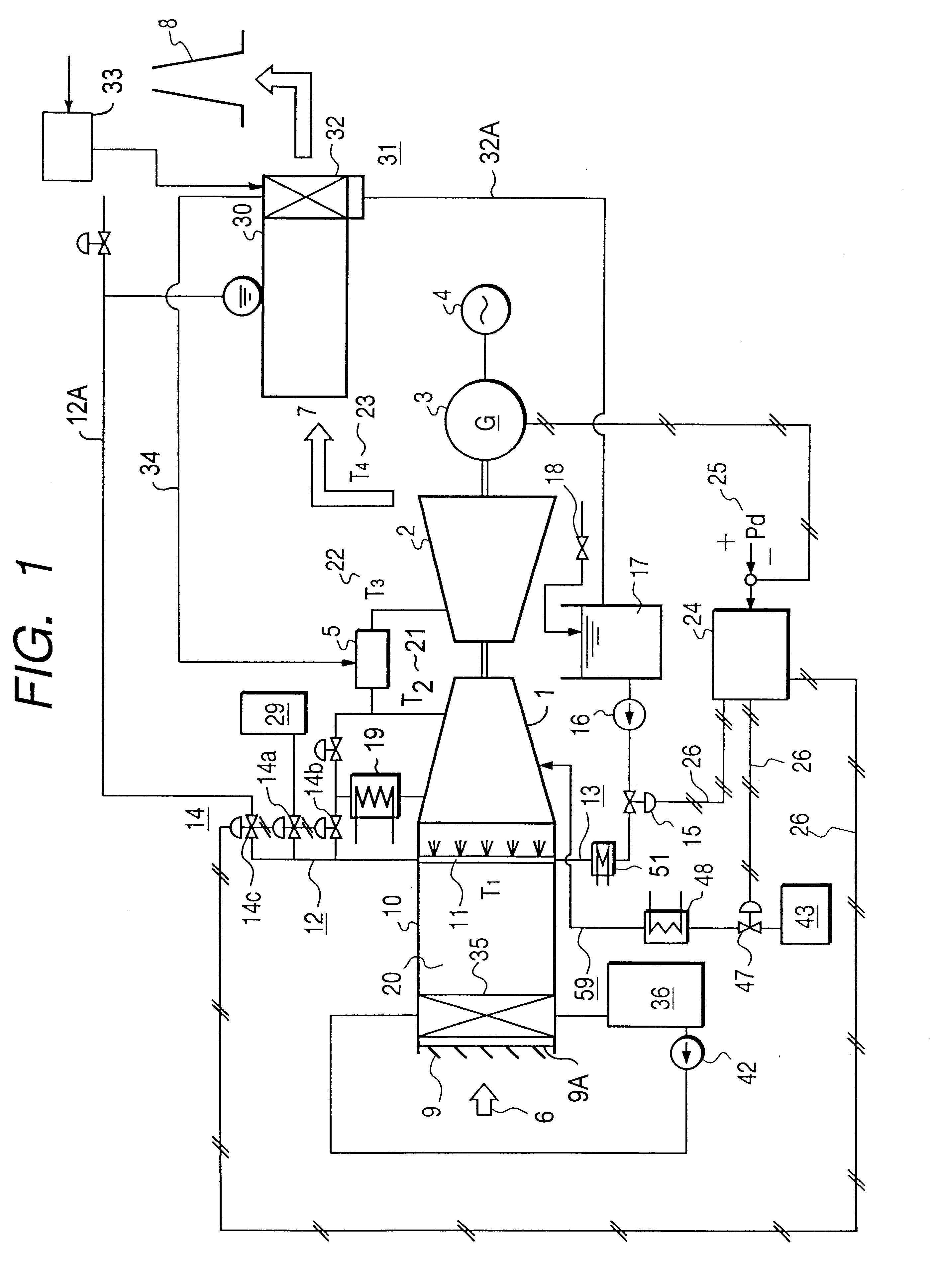
the present invention will be described with reference to FIG. 1.
A gas turbine of the embodiment of the present invention includes, as shown in FIG. 1, a compressor 1 for compressing and discharging gas, a combustor 5 to which the gas compressed by the compressor 1 is supplied, a turbine 2 driven by the combustion gas from the combustor 5, a generator 3 connected to a shaft of the turbine 2, and a electric power grid 4 for transmitting power generated by the generator 3. Exhaust gas 7 from the gas turbine is discharged into the atmospheric air through a stack 8.
In the following embodiment, it is assumed that the gas supplied to the compressor 1 is air.
An inlet air compartment 10 for taking in inlet air 6 to be supplied to the compressor 1 is connected to the compressor 1. Usually, a louver 9 disposed on the upstream side of the inlet air compartment 10. An air filter 9A is disposed adjacent the louver 9 on the compressor side (rear flow side). The air filter is provided immediately ...
second embodiment
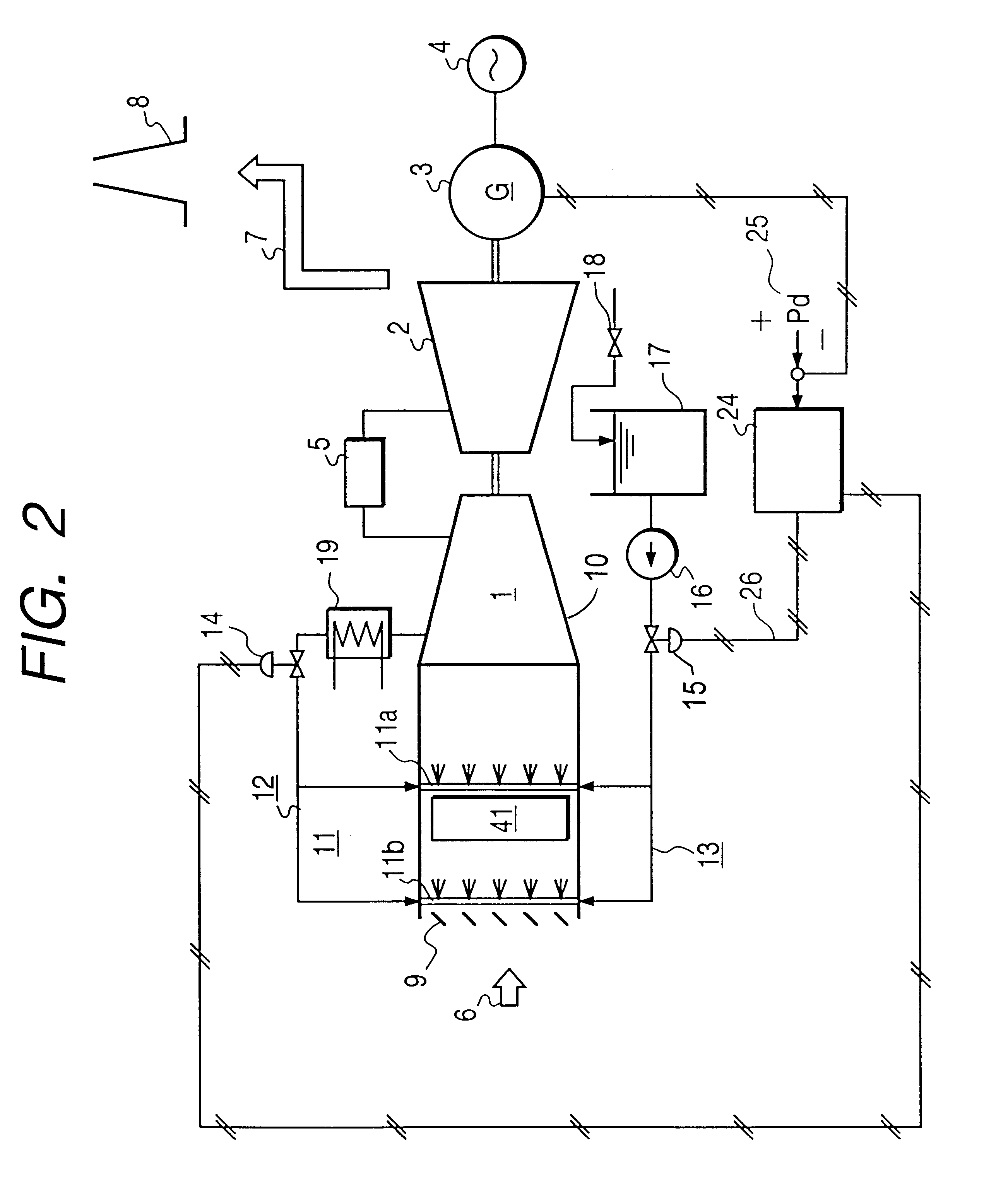
the present invention will be described with reference to FIG. 2. This embodiment clearly indicates, comparing with the first embodiment, that the atomizing nozzles 11 are positioned in the inlet air compartment adjacent the louver 9. FIG. 2 shows the atomizing nozzles 11 so as to facilitate understanding of the position of them. While FIG. 2 shows a construction which includes air supply means 12 for supplying pressurized inlet air, such air supply means 12 as in the embodiment 1 need not be provided only if such desired liquid droplets as described above are obtained.
From the point of view to promote evaporation prior to flowing in to the compressor 1 to raise the efficiency in cooling of inlet air, preferably the atomizing nozzles 11 are disposed in a spaced relationship from the entrance of the compressor 1 in this manner.
Describing in more detail, the atomizing nozzles 11 are suitably disposed at one of the positions 11a or 11b.
Where the inlet air compartment 10 includes a sile...
third embodiment
The third embodiment is constructed such that, in a gas turbine of the type wherein bleed extraction of the compressor 1 is supplied into a cooling flow path formed in a turbine blade to cool the turbine blade, the bleed extraction flow rate is controlled in response to the temperature of the bleed extraction of the compressor.
Instead of feeding compressed air to a mid stage of the compressor 1 of the type wherein a turbine blade is cooled, the flow rate after the bleed extraction stage can substantially be increased by decreasing the bleed extraction quantity from a bleed extraction line 56 of the compressor 1, which is provided for cooling the turbine blade, in conformity with a drop of the temperature of the bleed extraction gas.
To this end, a flow control valve 55 or a motor valve with an intermediate opening set is provided in the bleed extraction line 56.
If water droplets are evaporated to cool air in the compressor 1, then since also the temperature of the bleed extraction dr...
PUM
 Abstract
Description
Claims
Application Information