Pulse run-length measurement for HF data signal by dividing accumulated phase difference between first and second zero-crossings by single-cycle range using multiple cycle range sawtooth waveform

a technology of hf data and run-length measurement, applied in the field of digital signal processing, can solve problems such as phase errors, multiple sources of signal degradation, and loss-of-frame indications of compact disc players, and achieve the effect of reducing the number of hf data signal pulses, and reducing the number of hf data pulses

Inactive Publication Date: 2002-05-14
CEVA IRELAND +1
View PDF21 Cites 43 Cited by
  • Summary
  • Abstract
  • Description
  • Claims
  • Application Information

AI Technical Summary

Problems solved by technology

Compact disc (CD) players suffer from several sources of signal degradation.
In addition, disc imperfections such as "black dot" cause loss-of-signal indications, and scratches on the disc cause persistent loss-of-frame indications.
Also, excessive asymmetry may disturb the frame synchronization by causing, for example, an 11T/11T frame synchronization sequence to appear as a 10T/12T or 12T/10T sequence.
If the slicing threshold is not correct, errors in measured run lengths (pulse lengths in the input data waveform) and phase errors can result.
Finally, errors in angular velocity may cause signal distortion.
However, as can be seen from FIG. 1, there is no way

Method used


Image

  • Pulse run-length measurement for HF data signal by dividing accumulated phase difference between first and second zero-crossings by single-cycle range using multiple cycle range sawtooth waveform
  • Pulse run-length measurement for HF data signal by dividing accumulated phase difference between first and second zero-crossings by single-cycle range using multiple cycle range sawtooth waveform
  • Pulse run-length measurement for HF data signal by dividing accumulated phase difference between first and second zero-crossings by single-cycle range using multiple cycle range sawtooth waveform

Examples


Embodiment Construction

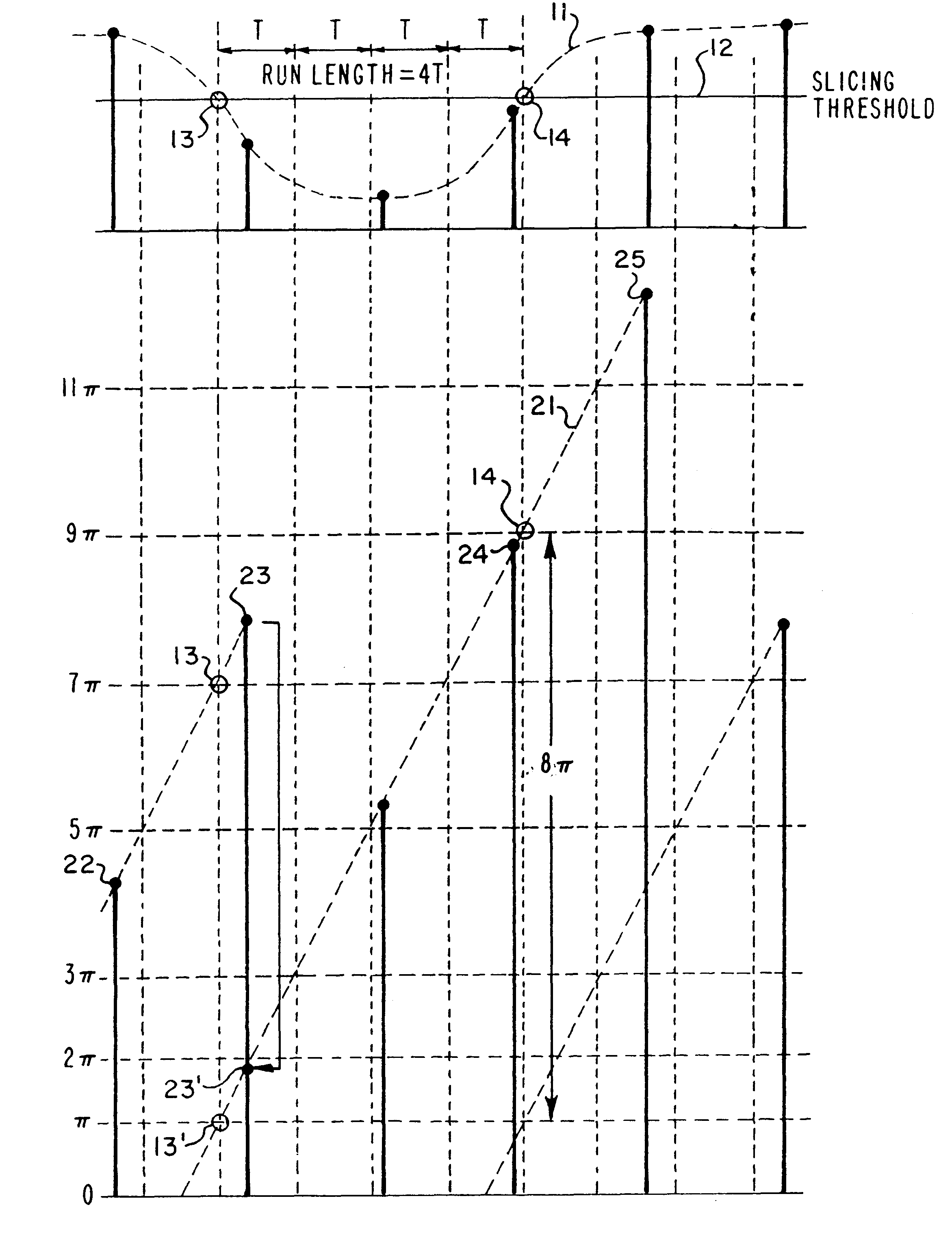
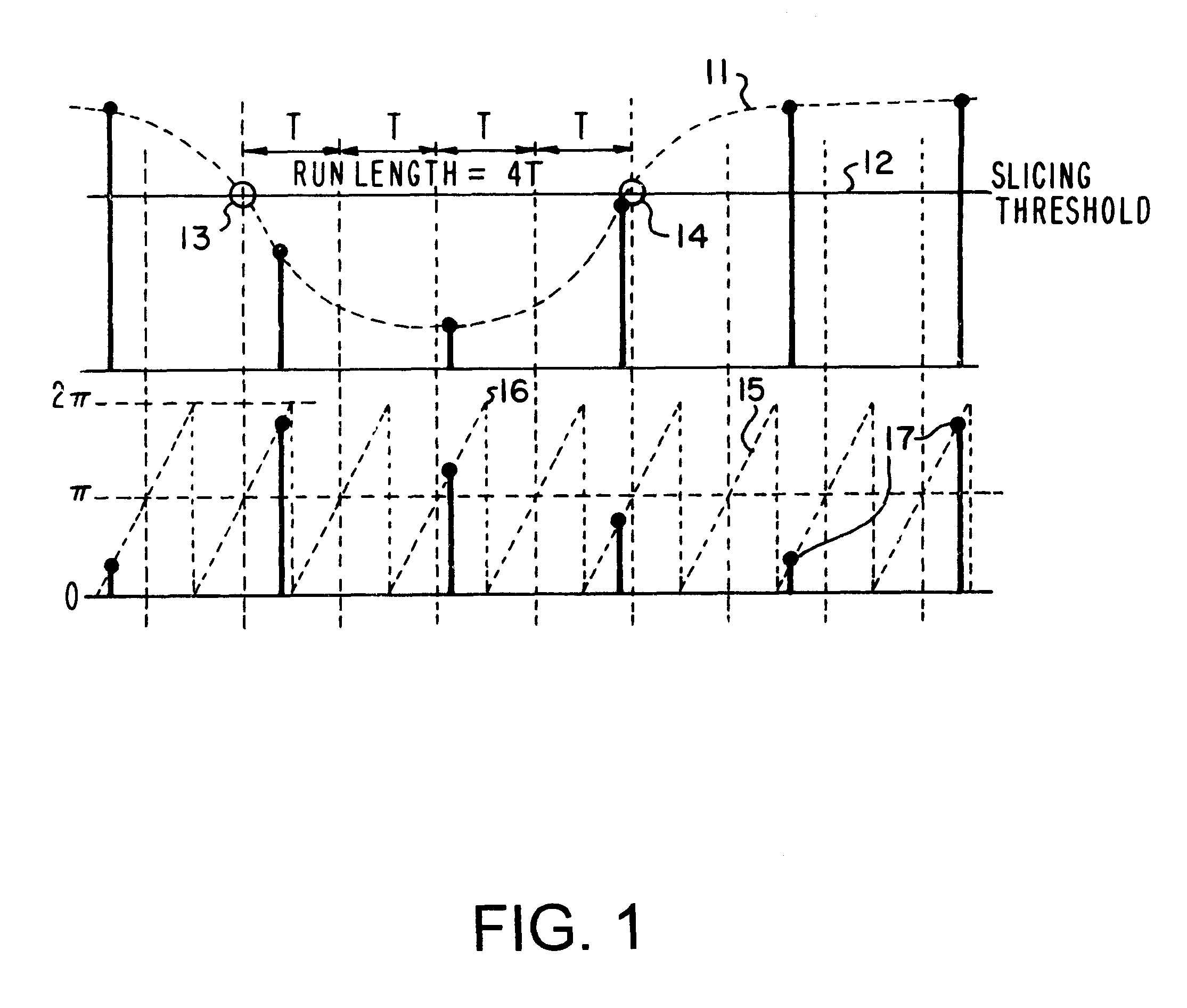
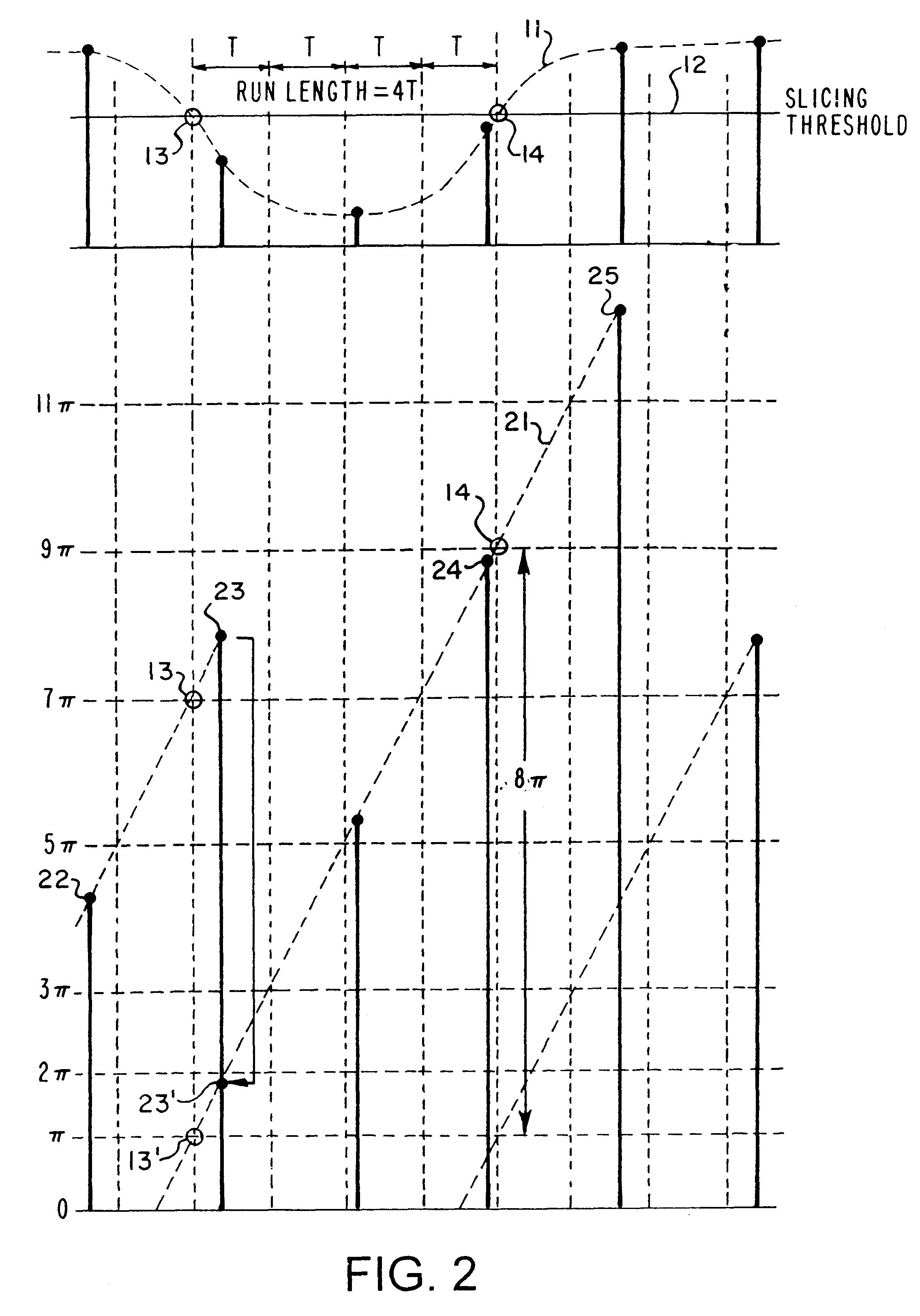
The present invention is a HF synchronization (hfSync) circuit which utilizes an All-Digital Phase Locked Loop (ADPLL) to recover a bit clock signal embedded in the HF signal from the pickup of a compact disc (CD) player. The ADPLL rejects high frequency phase fluctuations, but tracks low frequency phase variation. When there is a loss-of-signal indication (due, for example to black dot) or persistent loss of frame (due, for example to a scratch on the disc), the circuit free-runs until the error indication is removed. The hfSync circuit also corrects frame synchronization errors caused by excessive asymmetry, such as an 11T / 11T sequence appearing as a 10T / 12T or 12T / 10T sequence. The circuit also reports measured run lengths and phase errors which may be utilized to determine the correctness of the DC slicing operation performed on the HF pickup signal prior to its input to the hfsync circuit. The circuit also supports operation in the Constant Access Velocity (CAV) mode and in the...


PUM


Abstract

A system and method for accurately measuring a pulse run length in a high frequency (HF) data signal while utilizing a low analog-to-digital conversion (ADC) sampling rate. Four bits are added to the most significant end of an oscillator's accumulator register so that the oscillator generates a sawtooth clock waveform ranging in phase from zero (0) to 32pi radians. An interpolator detects a first zero-crossing transition of the HF data signal at the leading edge of the pulse run length, and a phase detector measures a first phase increment at that time. The MSBs of the accumulator register is then initialized to place the measured first phase increment in a range between zero (0) and 2pi radians. The accumulator register then accumulates phase increments until the interpolator detects a second zero-crossing transition of the HF data signal at the trailing edge of the pulse run length, and the phase detector measures a second phase increment when the second zero-crossing transition is detected. An accumulated phase difference is calculated by subtracting the initialized first phase increment from the measured second phase increment. The pulse run length is then obtained by dividing the accumulated phase difference by 2pi.

Description

1. Technical Field of the InventionThis invention relates to digital signal processing and, more particularly, to an all digital phase-locked loop (ADPLL) circuit and method of recovering a bit clock signal from a sampled waveform.2. Description of Related ArtCompact disc (CD) players suffer from several sources of signal degradation. For example, high-frequency phase fluctuations may be caused by jitter due to disc asymmetry. Low-frequency phase variation may be caused by wander due to player and / or disc eccentricity. In addition, disc imperfections such as "black dot" cause loss-of-signal indications, and scratches on the disc cause persistent loss-of-frame indications. Also, excessive asymmetry may disturb the frame synchronization by causing, for example, an 11T / 11T frame synchronization sequence to appear as a 10T / 12T or 12T / 10T sequence.The high frequency (HF) signal from the CD "pickup" is digitized, equalized (via digital filtering), and the direct current (DC) component is ...

Claims


Application Information

Patent Timeline
IPC IPC(8): G11B20/14H04L7/033G11B20/10
CPCG11B20/10037H04L7/0331G11B20/1403G11B20/10009G11B20/1426
Inventor BOWLES, LIAM
Owner CEVA IRELAND
Why Eureka
Try Eureka