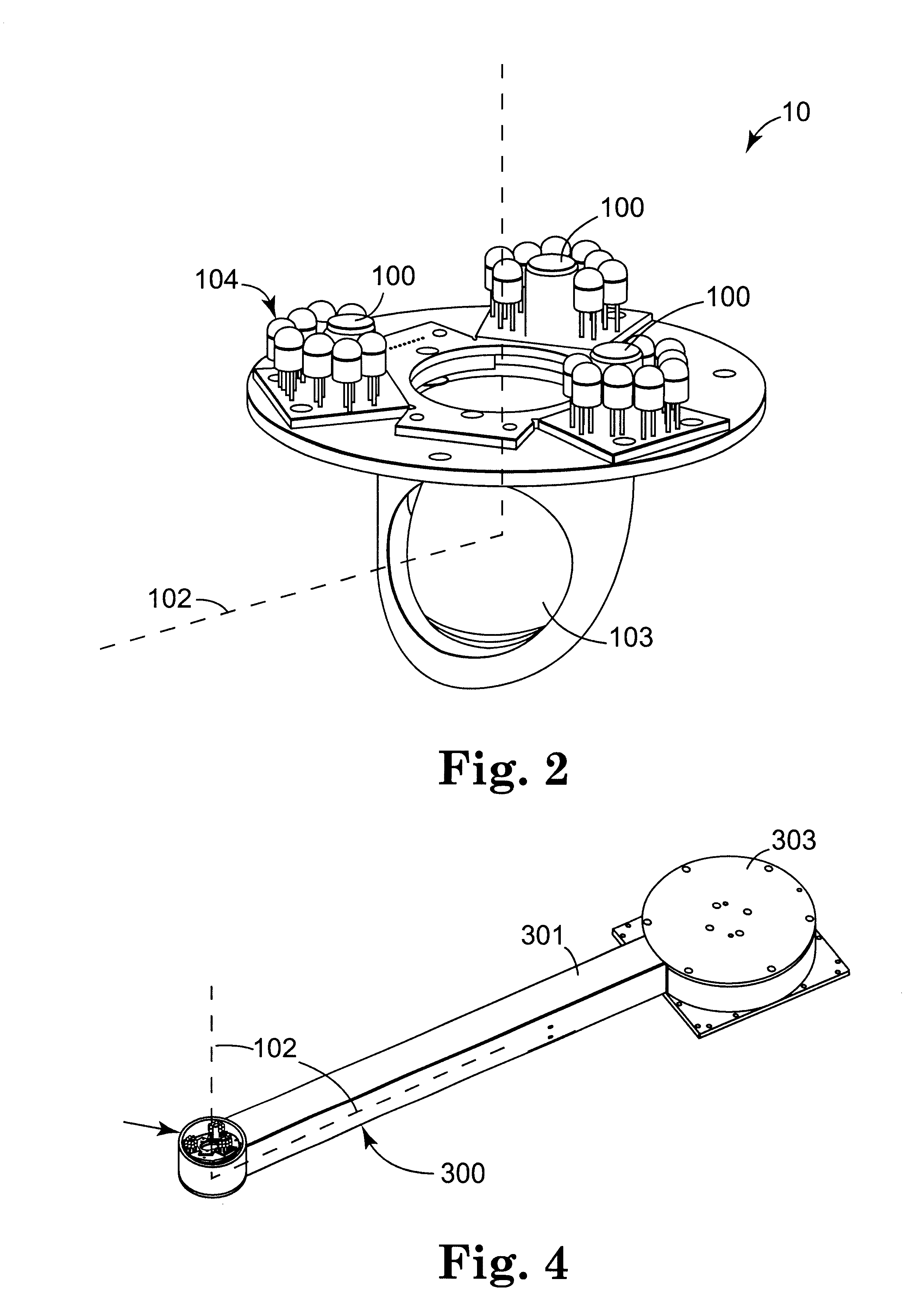
Optional mirror 103 permits measurement head 10 to be located in a preferred arm 300, as illustrated in FIG. 4, so that distances may be measured from below objects located above arm 300. The camera may be located within extension arm 301, remote from measurement head 10, which lengthens the
optical path but thereby enables the use of low cost optical components despite a relatively short working distance between measurement head 10 and target 120. Extension arm 301 may move laterally and / or may rotate about its central axis by any convenient means 303. These options accommodate relatively large objects and / or multiple distance measurements.
As compared to other optical measurement systems, one
advantage of the invention follows from the
crossover point
lying within the measurement range of the system. This permits the use of optical equipment having relatively narrow fields of view, which are physically smaller and thus suited for many applications in which equipment size is important (such as in-line industrial sensing, measurement, and other applications of
machine vision, particularly in the
semiconductor and
electronics industries). Yet, despite its relatively
narrow beam and
field of view, the invention provides relatively
high resolution, very accurate
distance measurement, and very high
repeatability. This can be compared to, for example, so-called scanning Moire interferometers, which provide accurate measurement but employ light projected at an
angle of incidence of approximately 45.degree. to the work surface, i.e., a
wide beam as compared to the invention. According to general principles of
optics, systems using such high beams are limited to apertures of approximately the same size, which are undesirable. In addition, such systems are subject to undesirable amounts of shadowing effects. Thus, for example, the invention is particularly well suited for measuring the depth of narrow holes.
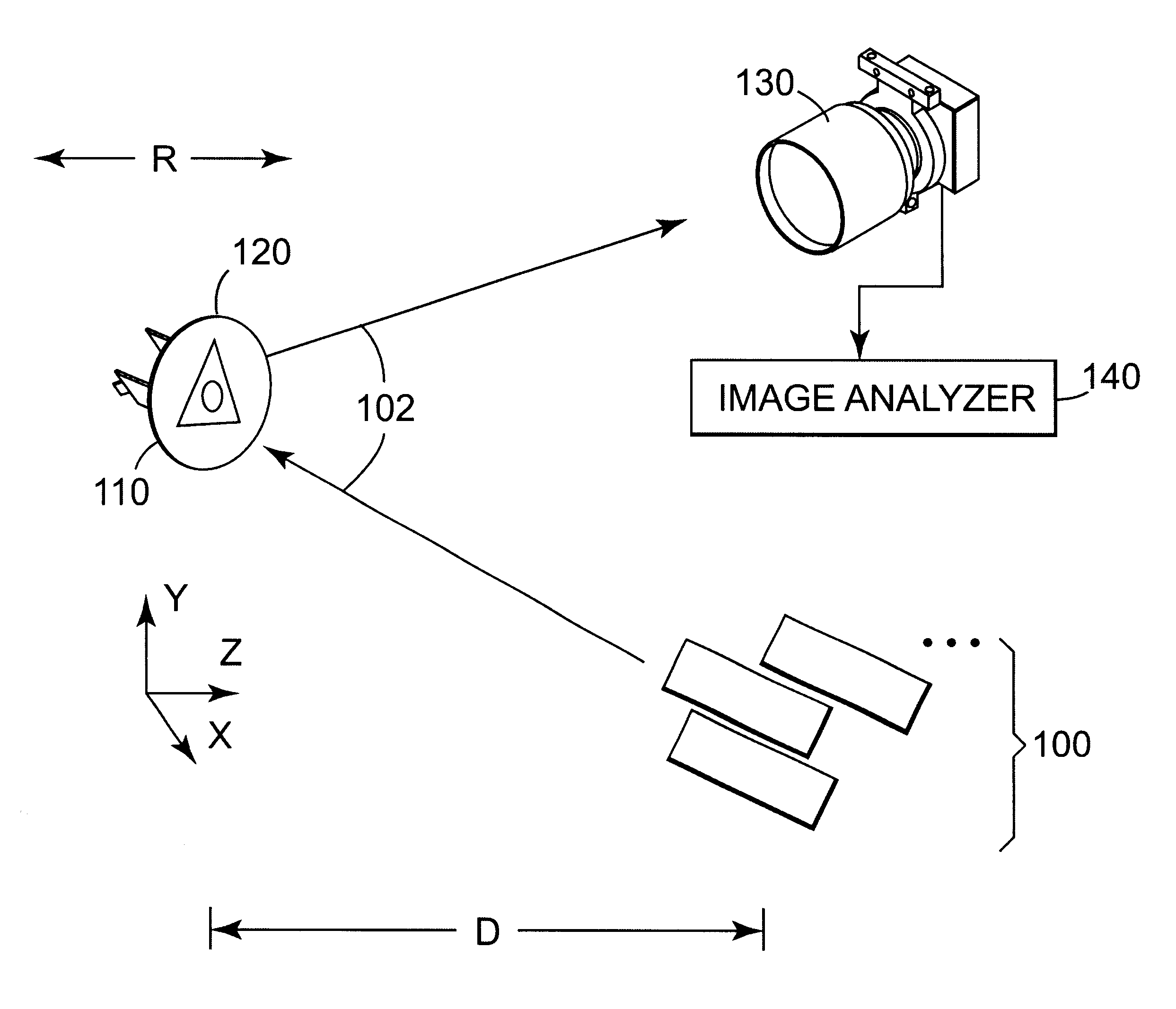
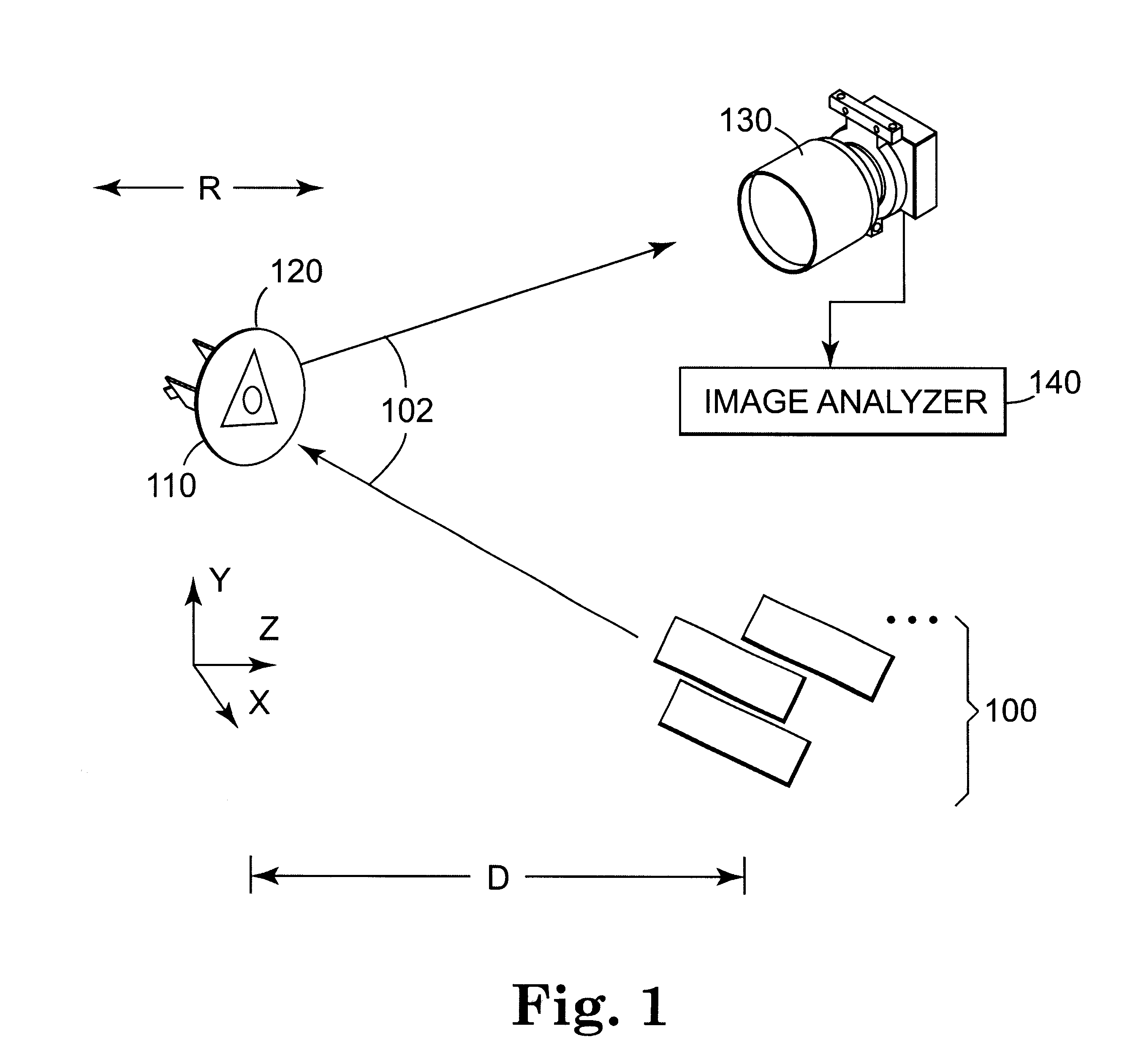
Depending on the
magnification of the optical system, distance to the
crossover point, and the
crossover angle, an accurate relationship can be determined between circumference of the triangle and true distance. Further, with careful
image processing the exact centerlines of each line projection can be determined, which greatly reduces the effect of
laser speckle, biasing and
distortion. Additionally, the use of a crossover point in the mid-range of triangle projection increases the sensitivity considerably, while at the same time providing a convenient geometry for alignment and calibration.
FIG. 5 is a perspective exploded view of a preferred embodiment of another aspect of the invention, a non-opaque reflecting target 200 that may be mounted to object 120 and on which two-dimensional geometric FIG. 110 may be projected. Use of any target is optional, but preferred, to increase range and sensitivity by reflecting a higher percentage of the light back toward the image device 130. In the preferred embodiment shown, target 200 comprises a fine-grained retroreflective material 201 mounted to a base 202 and covered with preferred protective layer 203, which may be attached to retroreflective material 201 with conventional transparent spray
adhesive. A center feature 204, which may be any arbitrary shape but is preferred to be a circle to simplify
image processing, lies within retroreflective material 201. Alternative configurations for center feature 204 include any polygon, crosshairs, etc. Center feature 204 may be located and used for centering of the
field of view of the cameras in accordance with known techniques, however, the invention is robust enough to tolerate off-center tolerances of as much as 0.5 inch without loss of overall system accuracy.
These parts may be assembled in any convenient manner, but it is particularly preferred to provide an appropriately sharp edge 205 on center feature 204 so that it may
cut out the center portion of retroreflective material 201 and press fit snugly into the center hole of base 202, thus positioning the surface of center feature 204 flush with the surface of retroreflective material 201. Target 200 may be mounted to the object in any convenient manner, such as by clip 206. Spacer 207 provides stability.
In operation, center feature 204 is kept generally centered in the camera
field of view, thus better maintaining symmetry for the
laser line and triangle projections. A contrasting feature at the center of the target enables image analyzer 140 to determine the X and Y displacements of the target within the camera field of view. This is aided by the addition of an additional illumination source selected for the camera sensitivity and aimed at the target. By placing the
light source near the camera
optical path (thus providing on-axis illumination), the retroreflective target also serves to direct light into the camera and enhancing the contrast of the target feature. The geometric center or outline of the feature is used to determine the target X and Y displacement relative to the camera field of view. A true measurement of X and Y offset from the optical center line can be calculated after calibrating the relationship between the
magnification and the distance, and by using the distance to the target determined by the laser measurement (or some other means). Also, the size of the image of center feature 204 provides an approximate measure of distance D.

