

Methods for the regeneration of a denitration catalyst
a denitration catalyst and catalyst technology, applied in the field of denitration catalyst regeneration methods, can solve the problems of reduced catalytic power, low regenerative effect of conventional cleaning methods using water or hydrochloric acid,
- Summary
- Abstract
- Description
- Claims
- Application Information
AI Technical Summary
Benefits of technology
Problems solved by technology
Method used
Image

Examples
example 2
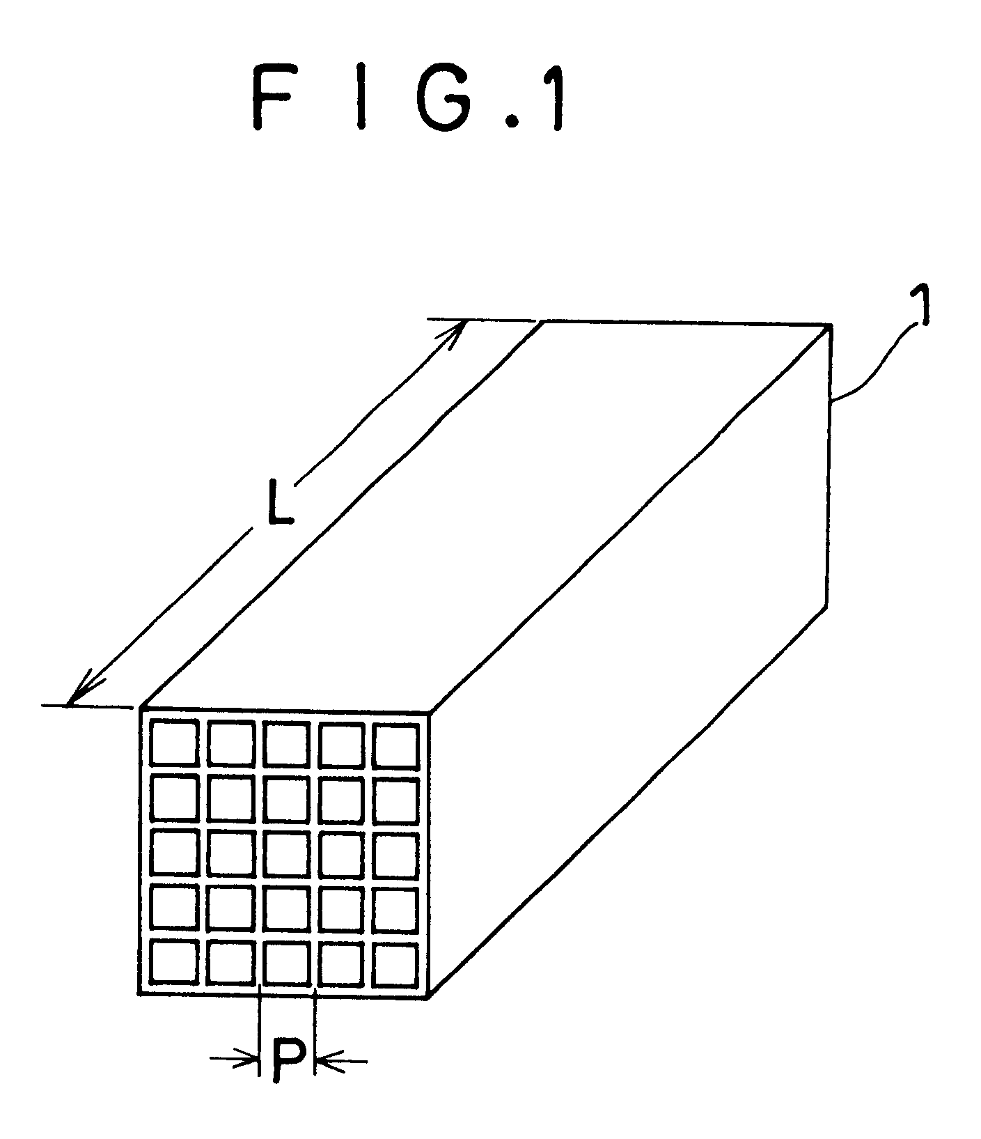
Denitration catalysts (composed of 89.2 wt. % of TiO.sub.2, 10.2 wt. % of WO.sub.3, and 0.6 wt. % of V.sub.2 O.sub.5) having a honeycomb configuration with a pitch of 7.4 mm were used in a coal-fired boiler plant B for about 55,000 hours.
In order to regenerate twelve denitration catalysts having reduced denitration power as a result of the aforesaid use, each of them was soaked in a cleaning fluid comprising a 5% aqueous solution of NaOH, KOH or Na.sub.2 CO.sub.3 so that the volume ratio of the cleaning fluid to the denitration catalyst was 4.0, allowed to stand at 60.degree. C. for 4 hours, washed with water, and then dried.
After the above-described alkali cleaning, the catalyst was soaked in an activating fluid comprising a 5 wt. % aqueous solution of HCl, HNO.sub.3, H.sub.2 SO.sub.4 or HF so that the volume ratio of the activating fluid to the catalyst was 4.0, allowed to stand at 40.degree. C. for 30 minutes, washed with water, and then dried. As shown in Table 3 below, the rege...
example 3
The unused catalysts and spent catalysts for coal-fired boiler plants A and B, the regenerated catalysts obtained in Examples 1 and 2, and the regenerated catalysts obtained in Comparative Examples 1 and 2 were comparatively tested for denitration power under the conditions shown in Table 1.
Moreover, with respect to each of the regenerated catalysts, its average arsenic content and its compressive strength were also measured.
The results thus obtained are shown in Tables 2 and 3. In Tables 2 and 3, the degree of denitration (%) and the compressive strength ratio are defined as follows.
Degree of denitration (%)={[(Inlet NO.sub.x content)-(Outlet NO.sub.x content)] / (Inlet NO.sub.x content)}.times.100
Compressive strength ratio=(Compressive strength of test sample) / (Compressive strength of unused catalyst)
TABLE 1
TABLE 3
It has been confirmed by these results that, when a catalyst having reduced denitration power due to the deposition of arsenic compounds on the catalyst surfaces is regene...
example 4
Denitration catalysts (composed of 89.2 wt. % of TiO.sub.2, 10.2 wt. % of WO.sub.3, and 0.6 wt. % of V.sub.2 O.sub.5) having a honeycomb configuration with a pitch of 7.4 mm as shown in FIG. 1 were used in exhaust gas from a coal-fired boiler plant A for about 23,000 hours.
In order to regenerate six denitration catalysts having reduced denitration power as a result of the aforesaid use, each of them was soaked in a cleaning fluid comprising an aqueous solution containing H.sub.2 SO.sub.4 at a concentration of 0.03%, 0.05%, 0.3%, 1%, 20% or 30% so that the volume ratio of the cleaning fluid to the denitration catalyst was 4.0, allowed to stand at 20.degree. C. for 4 hours, washed with water, and then dried.
The regenerated catalysts thus obtained are referred to as "Catalysts 101-106" in order of increasing sulfuric acid concentration.
Moreover, in order to regenerate five other denitration catalysts having reduced denitration power as a result of the aforesaid use, each of them was so...
PUM
| Property | Measurement | Unit |
|---|---|---|
| temperature | aaaaa | aaaaa |
| temperature | aaaaa | aaaaa |
| temperature | aaaaa | aaaaa |
Abstract
Description
Claims
Application Information