Data storage system and methods using diffractive near-field optics

Inactive Publication Date: 2002-05-28
AVAGO TECH WIRELESS IP SINGAPORE PTE
View PDF15 Cites 65 Cited by
  • Summary
  • Abstract
  • Description
  • Claims
  • Application Information

AI Technical Summary

Benefits of technology

There is shown in FIG. 1 a conventional optical data storage and retrieval system 10 used with an optical storage medium 30, such as a CD-ROM. System 10 comprises an objective lens 11, a beam-splitter 13, a detector 15 such as a photodiode, a focusing lens 17, and a source of illumination 19 such as a laser device. System 10 also comprises an aplanatic hemisphere 21 where objective lens 11 and hemisphere 21 are controlled by means of a servo system 23. Alternatively, a modulator 25 may be used in conjunction with illumination source 19. During the process of storing or retrieving data, optical storage medium 30 is moved relative to hemisphere 21 as indicated by the arrow, and data, comprising surface pits or other artifacts, is read from or written to optical storage medium 30.
In another prior-art system, shown in FIG. 2, data from optical storage medium 30 is accessed by a conventional optical system 40 comprising an objective lens 41, such as a Digital Versatile Disc (DVD) lens, and a solid immersion lens 43. Illumination 45 enters solid immersion lens 43 at an angle greater than the critical angle .theta..sub.C and is totally internally reflected from a reflection surface 44 as reflected radiation 47. Solid im

Problems solved by technology

Total internal reflection (TIR) of light within a transparent body results in an evanescent field leaking beyond the body.
Steeply curved optics such as aplanatic hemisphere 21 and solid immersion lens 43 are typically produced individually and, as such, are expensive to manufacture.
However, it still remains difficult to control the quality of the optical surface because of the large shrinkage involved.
Plastic molding is possible, but the refractive indices

Method used


Image

  • Data storage system and methods using diffractive near-field optics
  • Data storage system and methods using diffractive near-field optics
  • Data storage system and methods using diffractive near-field optics

Examples


Embodiment Construction

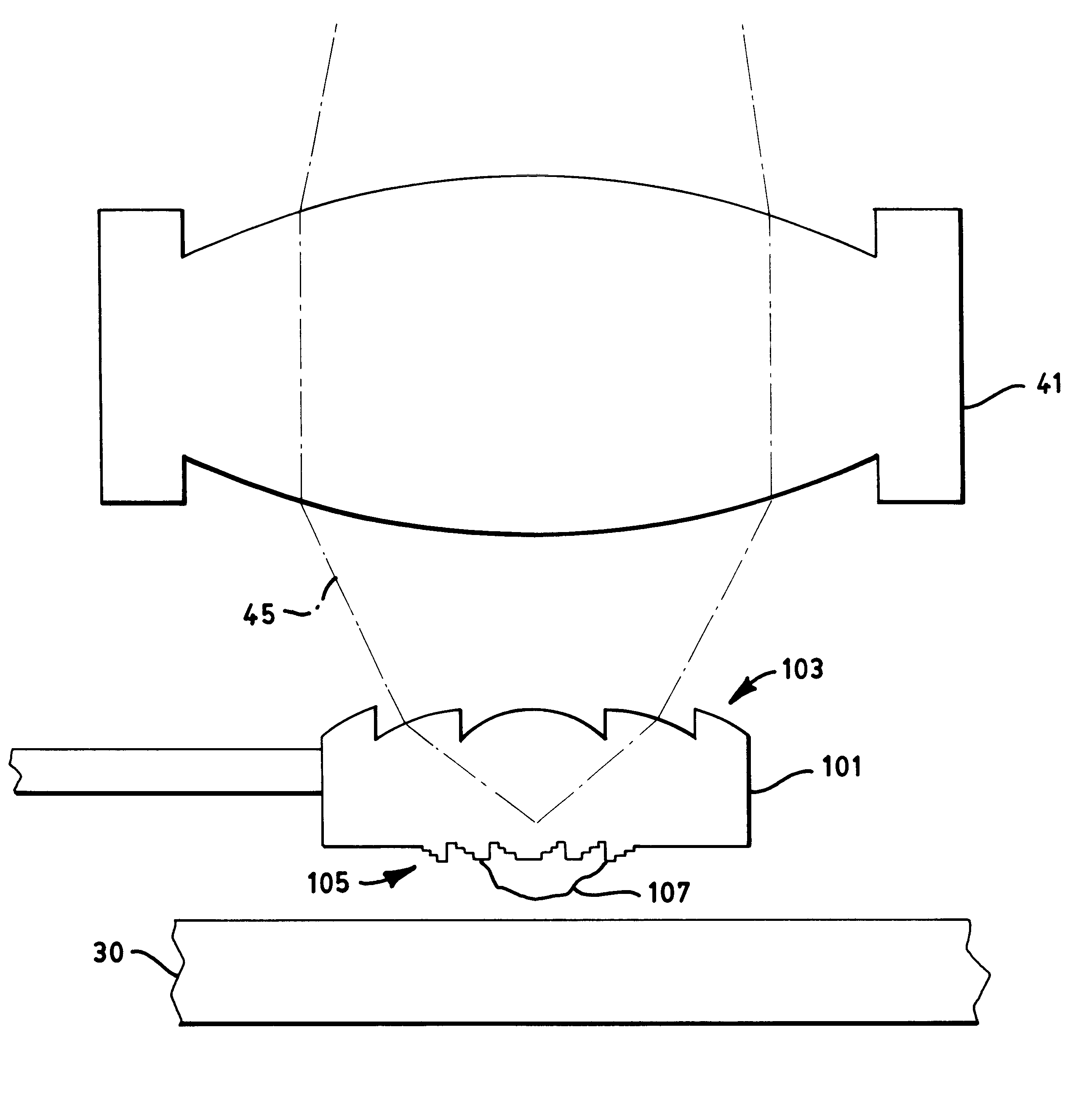
There is shown in FIGS. 3 and 4 a first embodiment of an optical system 60 in accordance with the present invention. Optical system 60 comprises objective lens 41 and diffractive near-field optical element 63 (shown here in cross-sectional profile). Diffractive near-field optical element 63 is typically part of a "flying optical head" assembly, as well known in the relevant art. Diffractive near-field optical element 63 comprises a diffractive surface 66 in the form of Fresnel zone plates. The optical geometry of diffractive surface 66 is such that diffractive near-field optical element 63 is the optical equivalent of an aplanatic sphere. Diffractive near-field optical element 63 has a focal point at an internal total reflection surface 65. Diffractive surface 66 directs illumination 45 to internal total reflection surface 65 at beyond the critical angle, thereby forming an evanescent or near-field at surface 65. Diffractive surface 66 may have circular symmetry, as best seen in FIG...


PUM


Abstract

An optical assembly suitable for use with an optical medium for the storage and retrieval of data, the optical assembly comprising: a source of illumination for providing a beam of optical radiation, an objective lens disposed in the optical path of the beam for redirecting the beam to the optical medium, and a diffractive optical element disposed between the redirected beam of radiation and the optical medium such that at least a portion of the redirected beam of radiation passes through a surface of the diffractive optical element and is reflected to the objective lens.

Description

1. Field of the InventionThis invention in general relates to the field of data storage and retreival, including recording and micro-lithography, and in particular to data storage and retrieval systems incorporating flying diffractive near-field optical elements.2. Description of the Prior ArtGuerra and Plummer in 1987 first described and broadly claimed the application of evanescent field, now sometimes known as near-field, optics to a flying head, with the head flying in proximity to a rotating data storage media. Total internal reflection (TIR) of light within a transparent body results in an evanescent field leaking beyond the body. The light and TIR are frustrated when another body is brought within the decaying evanescent field, as first demonstrated by Newton in the 1600's and studied by hundreds of researchers over the years, up to this day. Images of the optical data in a compact disc obtained with the evanescent field from an Amici sphere are shown and described by Guerra ...

Claims


Application Information

Patent Timeline
IPC IPC(8): G11B7/135G11B7/12G11B9/00
CPCB82Y10/00G11B7/122G11B7/1387G11B7/1353G11B9/14
Inventor GUERRA, JOHN M.MOKRY KENDRA, PATRICIA A.
Owner AVAGO TECH WIRELESS IP SINGAPORE PTE
Why Eureka
Try Eureka