Fuel cell and separator for fuel cell

a technology of separator and fuel cell, which is applied in the direction of cell components, electrochemical generators, soldering apparatus, etc., can solve the problems of restricting the size reduction of the fuel cell, the separator formed of titanium, and the separator formed of carbon materials, so as to suppress corrosion and deterioration of the separator, and reduce the weight

Inactive Publication Date: 2002-06-11
AISIN TAKAOKA CO LTD +1
View PDF7 Cites 26 Cited by
  • Summary
  • Abstract
  • Description
  • Claims
  • Application Information

AI Technical Summary

Benefits of technology

Since the separator for the fuel cell according to the present invention is mainly comprised of an aluminum-based substrate, it can be reduced in weight. Moreover, since various plating layers are layered in the above-described order on the aluminum-based substrate constituting the separator, it is possible to suppress corrosion and deterioration of the separator.

Problems solved by technology

Namely, the separator formed of a carbon material is highly expensive because of the high cost of the material itself.
In addition, since the material is brittle, the separator is increased in thickness, thus restricting reduction in size of the fuel cell.
On the other hand, the separator formed of titanium, which is meritorious for size reduction because of its superior strength, is not meritorious for cost reduction because of its high material cost, nor sufficient for weight reduction because of its specific gravity.
In the separator constituting a fuel cell, since an electrically conductive path is produced along its direction of thickness, it is not desirable that an oxide film be formed on a surface layer of an aluminum-based material constituting the separator.
It is therefore not desirable to process the separator formed of the aluminum-based material with anodic oxidation to generate an anodic oxide film.
Thus, the fuel cell with a built-in separator formed of the aluminum-based material is not sufficient in durability against corrosion.

Method used


Image

  • Fuel cell and separator for fuel cell
  • Fuel cell and separator for fuel cell
  • Fuel cell and separator for fuel cell

Examples


examples

Referring to the drawings, embodiments of the present invention, as applied to a polymer solid electrolyte fuel cell, are explained.

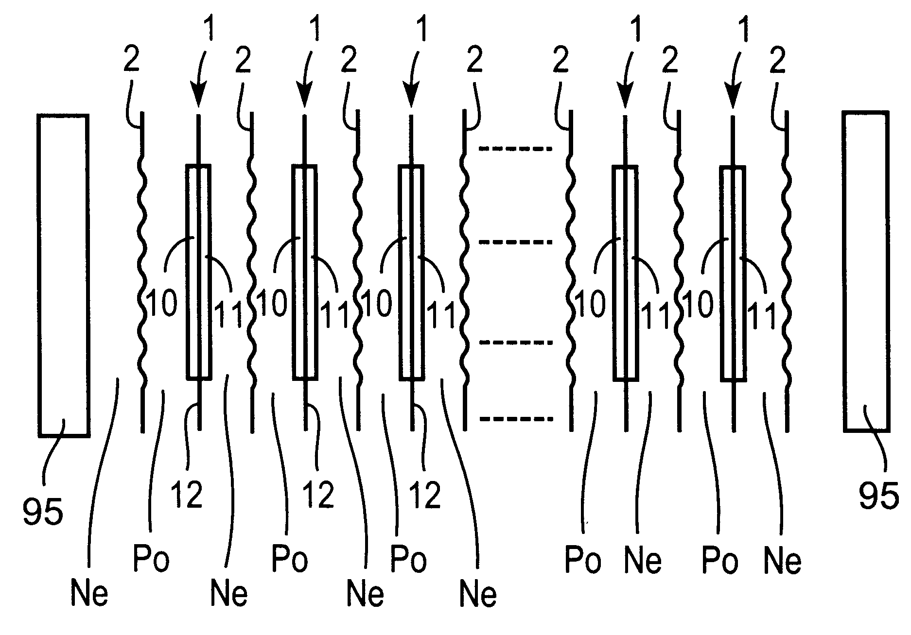
FIG. 1 schematically shows a layered structure of the polymer solid electrolyte fuel cell.

Referring to FIG. 1, plural unit cells 1 are arrayed in juxtaposition at a pre-set interval between outer frames 95, 95. Each unit cell 1 is made up of a positive electrode (anode, i.e., a "cathode" according to U.S. standard terminology) 10 and a negative electrode (cathode, i.e., an "anode" according to U.S. standard terminology) 11 constituting paired electrodes and a film-shaped polymer solid electrolyte membrane 12 exhibiting proton transmitting properties and which is sandwiched between the positive electrode 10 and the negative electrode 11.

As may be understood from FIG. 1, a separator 2 operating as an active material separator partitioning a negative electrode chamber Ne and a positive electrode chamber Po in a back-to-back relation. The negative electrode...

applied examples

FIG. 7 shows an applied example, in which a rubber layer 80 is layered integrally on the surface of the aluminum-based substrate 6, and a rubber layer 82 is layered integrally on the back surface of the aluminum-based substrate 6. The unit cell 1 is made up of a positive electrode 10 and a negative electrode 11, constituting paired electrodes, and a film-shaped high-molecular solid electrolytic film 12, exhibiting protonic transmission properties and which is sandwiched between the positive electrode 10 and the negative electrode 11. As may be understood from FIG. 7, the separator 2, functioning as a separator of the active material, defines the negative electrode chamber Ne and the positive electrode chamber Po in a back-to-back relation to each other. The negative electrode chamber Ne faces the negative electrode 11 and is fed with an active material of the negative electrode, such as a hydrogen-containing gas. The positive electrode chamber Po faces the negative electrode 11 and ...


PUM

PropertyMeasurementUnit
thicknessaaaaaaaaaa
thicknessaaaaaaaaaa
thicknessaaaaaaaaaa

Abstract

A fuel cell and a separator for same meritorious in reducing the weight and improving resistance against corrosion. In a fuel cell having a separator 2, the separator 2 includes an aluminum-based substrate 6, an intermediate plating layer layered on the aluminum-based substrate 6 and a noble metal layer 72 layered on the intermediate plating layer. The intermediate plating layer can be made up of a zinc-substitution plating layer 70 and a copper plating layer 71. The noble metal layer 72 can be a silver plating layer.

Description

This invention relates to a fuel cell including a separator formed of an aluminum-based material, and a separator for a fuel cell formed of an aluminum-based material.A fuel cell is comprised of a plurality of unit cells arranged at a pre-set distance from one another along the direction of thickness, each unit cell being made up of a positive electrode and a negative electrode constituting a pair of electrodes, and an electrolyte film sandwiched between said positive and negative electrodes. In this fuel cell, the positive electrode faces a positive electrode chamber fed with an active material for the positive electrode, while the negative electrode faces a negative electrode chamber fed with an active material for the negative electrode. In this fuel cell, the negative electrode chamber, fed with the active material for the negative electrode, is partitioned by a separator from the positive electrode chamber, and fed with the active material for the positive electrode.In the fuel...

Claims


Application Information

Patent Timeline
Patent Type & Authority Patents(United States)
IPC IPC(8): H01M8/02
CPCH01M8/0206H01M8/0228H01M8/0271Y10T428/1275Y02E60/50Y10T428/12792H01M2300/0082
Inventor MIZUNO, MASAHIROMATSUKAWA, MASANORI
Owner AISIN TAKAOKA CO LTD
Why Eureka
Try Eureka