Method and apparatus for improving efficiency of high-power linear amplifier

Inactive Publication Date: 2002-07-09
LUCENT TECH INC +1
View PDF18 Cites 37 Cited by
  • Summary
  • Abstract
  • Description
  • Claims
  • Application Information

AI Technical Summary

Benefits of technology

The present disclosure pertains to a method and apparatus for improving thermal efficiency and reliability of a linear power amplifier of a communication system. In an illustrative embodiment, the communication system operates in a half-duplex mode in which information signals are transmitted and received in alternating time intervals. A transistor control terminal (e.g., gate)

Problems solved by technology

Unfortunately, efficiency of the base station amplifier is inversely related to its linearity.
Typically, strict linearity requirements in modern wireless communication syst

Method used


Image

  • Method and apparatus for improving efficiency of high-power linear amplifier
  • Method and apparatus for improving efficiency of high-power linear amplifier
  • Method and apparatus for improving efficiency of high-power linear amplifier

Examples


Example

A preferred embodiment of the invention will now be described as having particular utility within a terrestrial base station of a wireless communication system. It is understood, however, that this application is merely exemplary and that the invention may have other useful applications such as within a satellite repeater or within a broadcasting system.

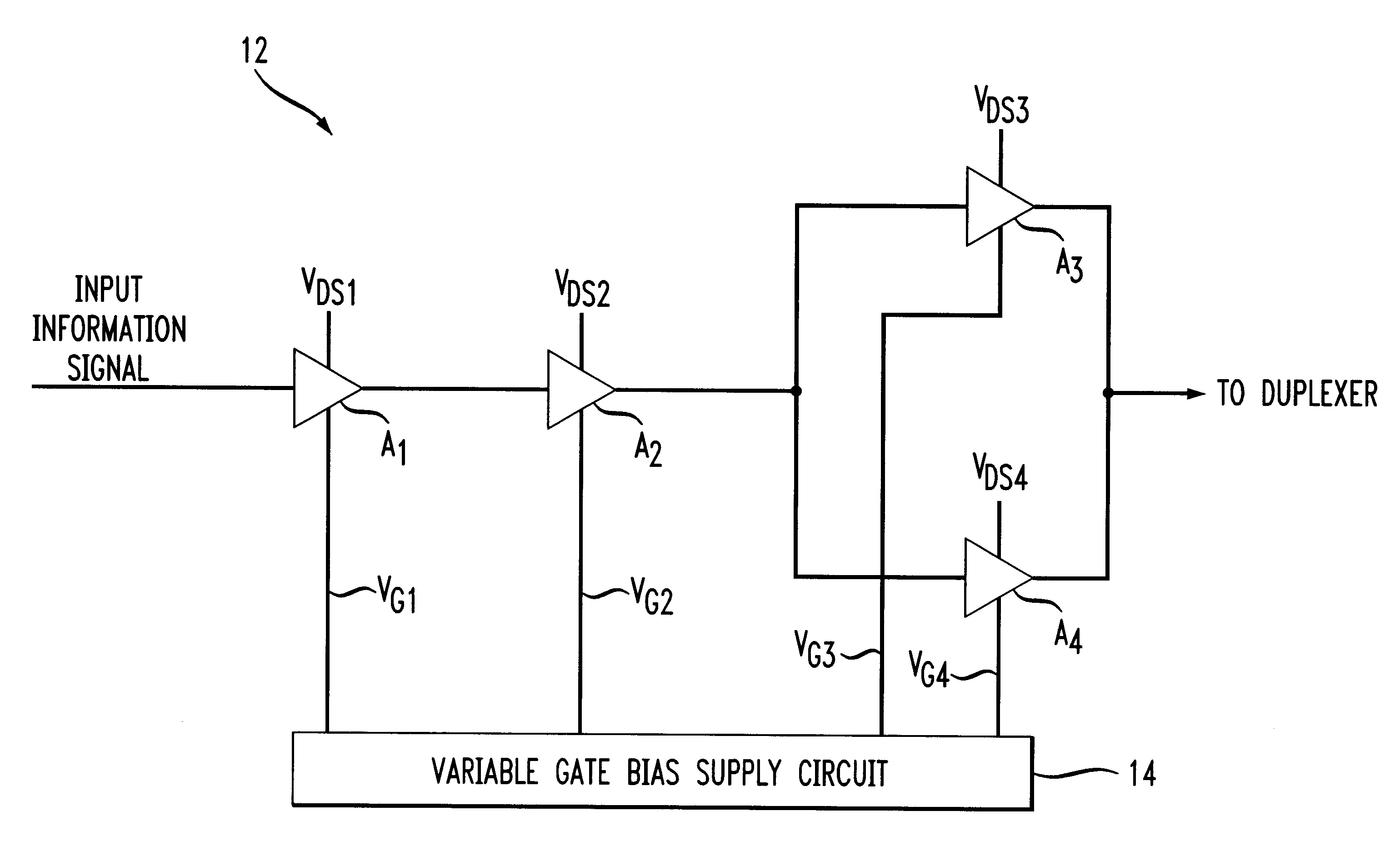
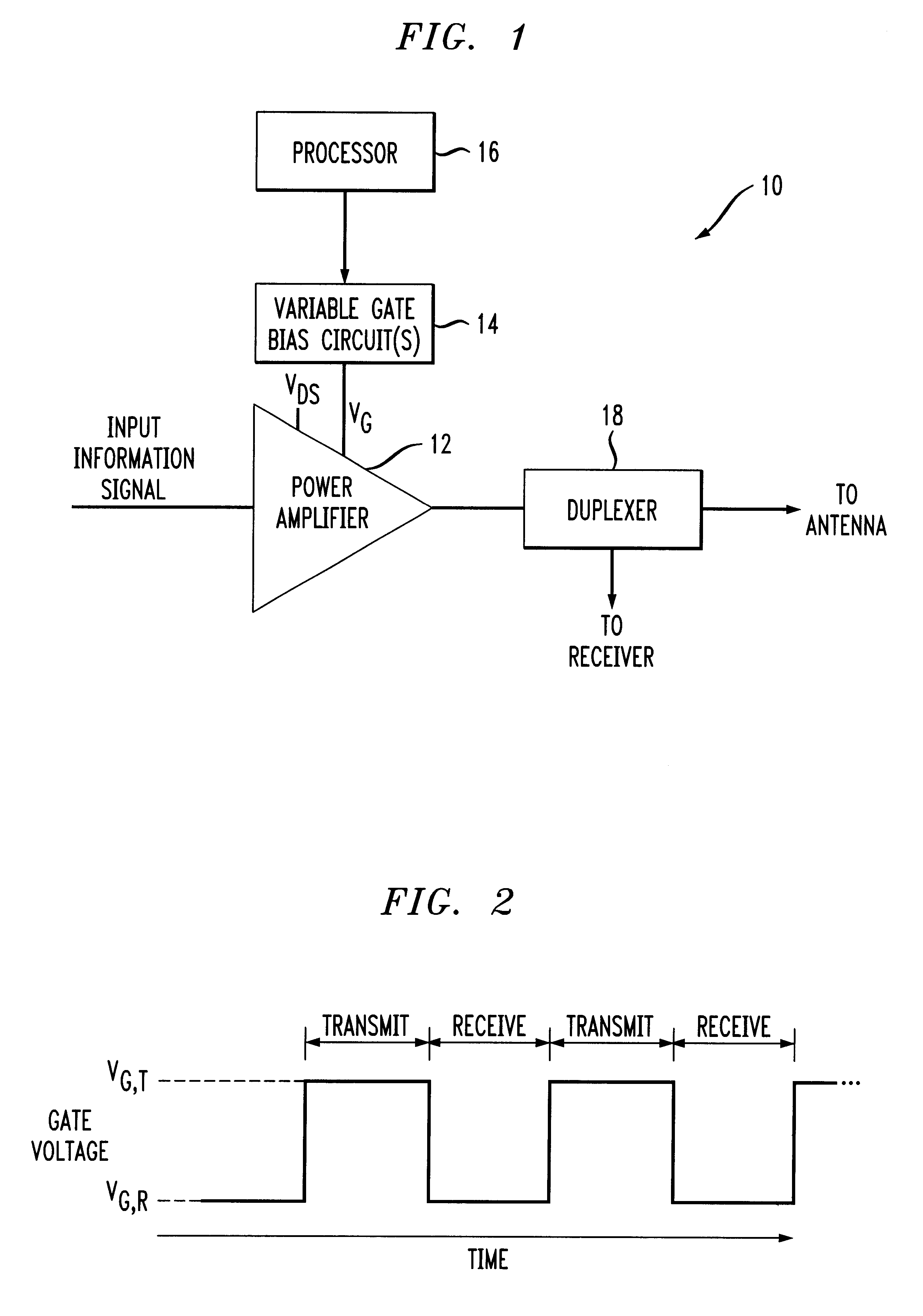
Referring now to FIG. 1, an illustrative embodiment of a transmitter 10 in accordance with the present invention is schematically shown in a simplified block diagram. Transmitter 10 is comprised of a power amplifier 12, a variable gate bias circuit 14, a processor 16 which controls an output gate voltage V.sub.G of bias circuit 14, and a duplexer 18 coupled to the output of power amplifier 12. Power amplifier 12 is typically a radio or microwave frequency, multiple stage amplifier that amplifies a modulated input information signal to a power level in the range of several watts to 100 watts or more, depending on the application. The ...


PUM


Abstract

Disclosed is a method and apparatus for improving thermal efficiency and reliability of a linear power amplifier of a communication system. In an illustrative embodiment, the communication system operates in a half-duplex mode and a transistor control terminal (e.g., gate) of the amplifier is biased at a first bias voltage during transmit intervals of the half-duplex mode. The control terminal is biased at a second bias voltage different from the first bias voltage during receive intervals. The second bias voltage is sufficient to reduce idle currents in the amplifier during the receive intervals, thereby improving thermal efficiency of the amplifier. Also disclosed is a base station including a base station controller, a variable bias control circuit and a linear power amplifier. The variable bias control circuit operates under the control of the base station controller to supply a variable bias voltage to the amplifier. Thermal efficiency of the amplifier is improved by reducing idle currents via appropriate bias voltage control during a weak signal transmitting mode and/or during receive intervals of a half-duplex operating mode.

Description

The present invention relates generally to wireless communications. More particularly, the invention relates to a method and apparatus for improving efficiency of a high power linear amplifier employed in a base station of a wireless communications system.Base stations of contemporary wireless communications systems (e.g., cellular telephone systems) typically employ a number of high power linear amplifiers to amplify information signals destined for wireless communication terminals (e.g., cellular telephones, personal communication devices, etc.) For instance, in frequency division multiple access (FDMA) systems, each high power amplifier usually amplifies a multi-carrier signal, with each carrier modulated with voice and data information destined for a particular wireless terminal. The communication channel associated with each carrier is narrowband, typically about 25-30 KHz wide. Hence, the high power amplifier must be highly linear to avoid generating intermodulation distortion...

Claims


Application Information

Patent Timeline
IPC IPC(8): H03F1/02H03F3/72H03F3/20H04B1/04H04W88/08H04W88/14
CPCH03F1/0261H03F3/72H03F1/30H03F2200/372H03F2203/7206H03F2203/7236
Inventor MORRAR, SAM
Owner LUCENT TECH INC
Why Eureka
Try Eureka