

SPR sensor cell and immunoassay apparatus using the same
a technology of immunoassay and sensor cell, which is applied in the field of immunoassay apparatus, can solve the problems of difficult to form thin metal film appropriately, difficult to fix antibody, and difficulty in forming thin metal film appropriately
- Summary
- Abstract
- Description
- Claims
- Application Information
AI Technical Summary
Benefits of technology
Problems solved by technology
Method used
Image

Examples
embodiment 24
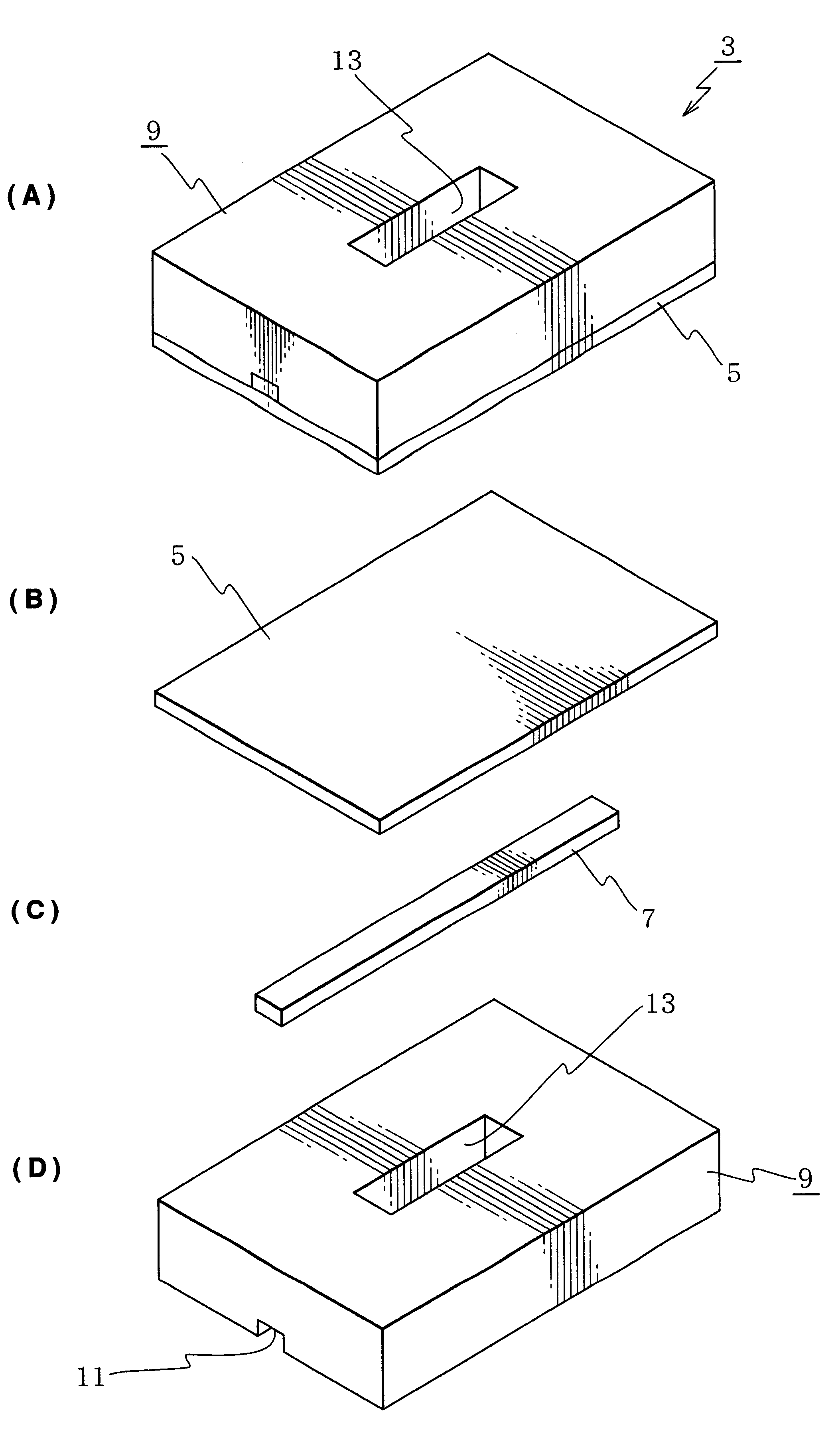
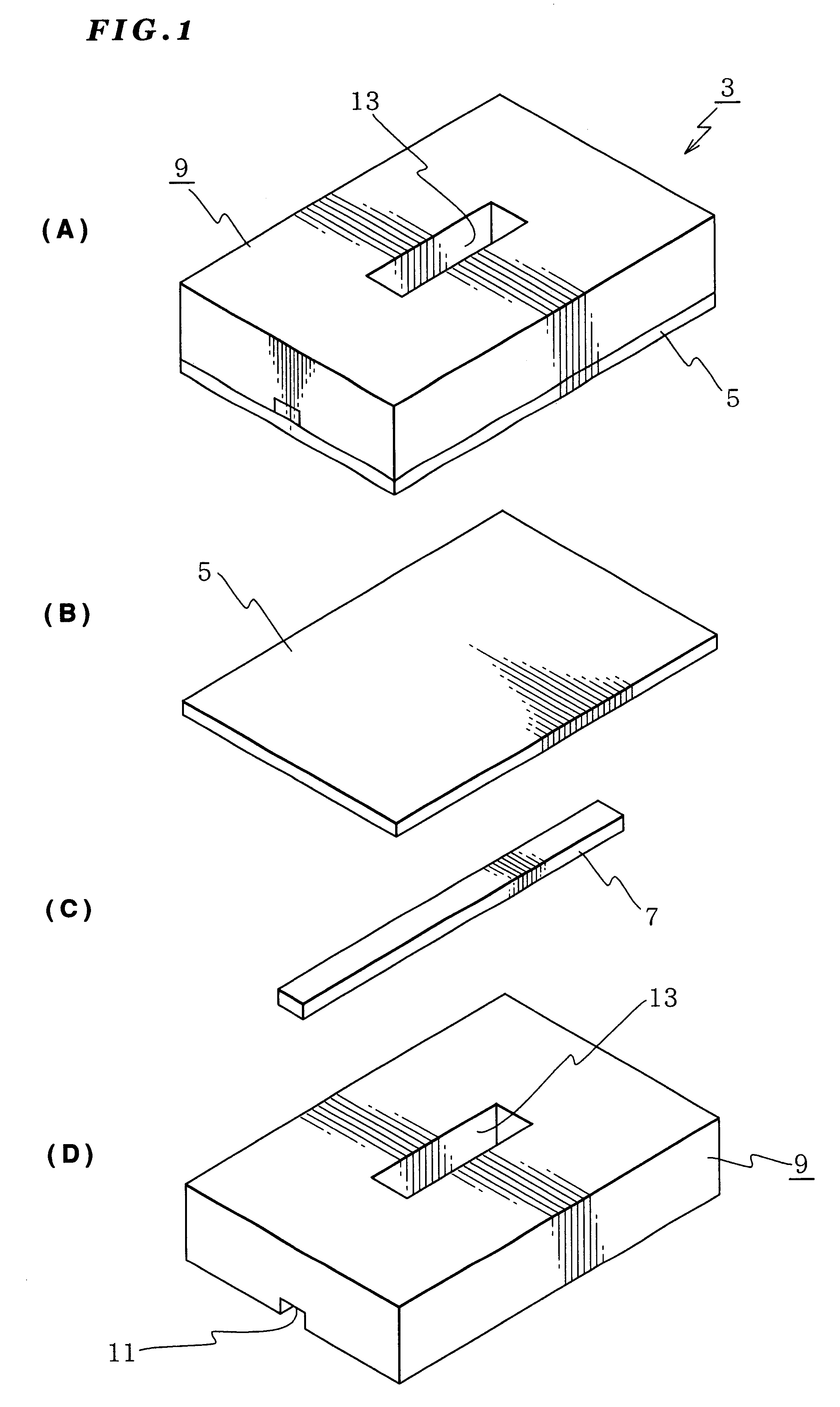
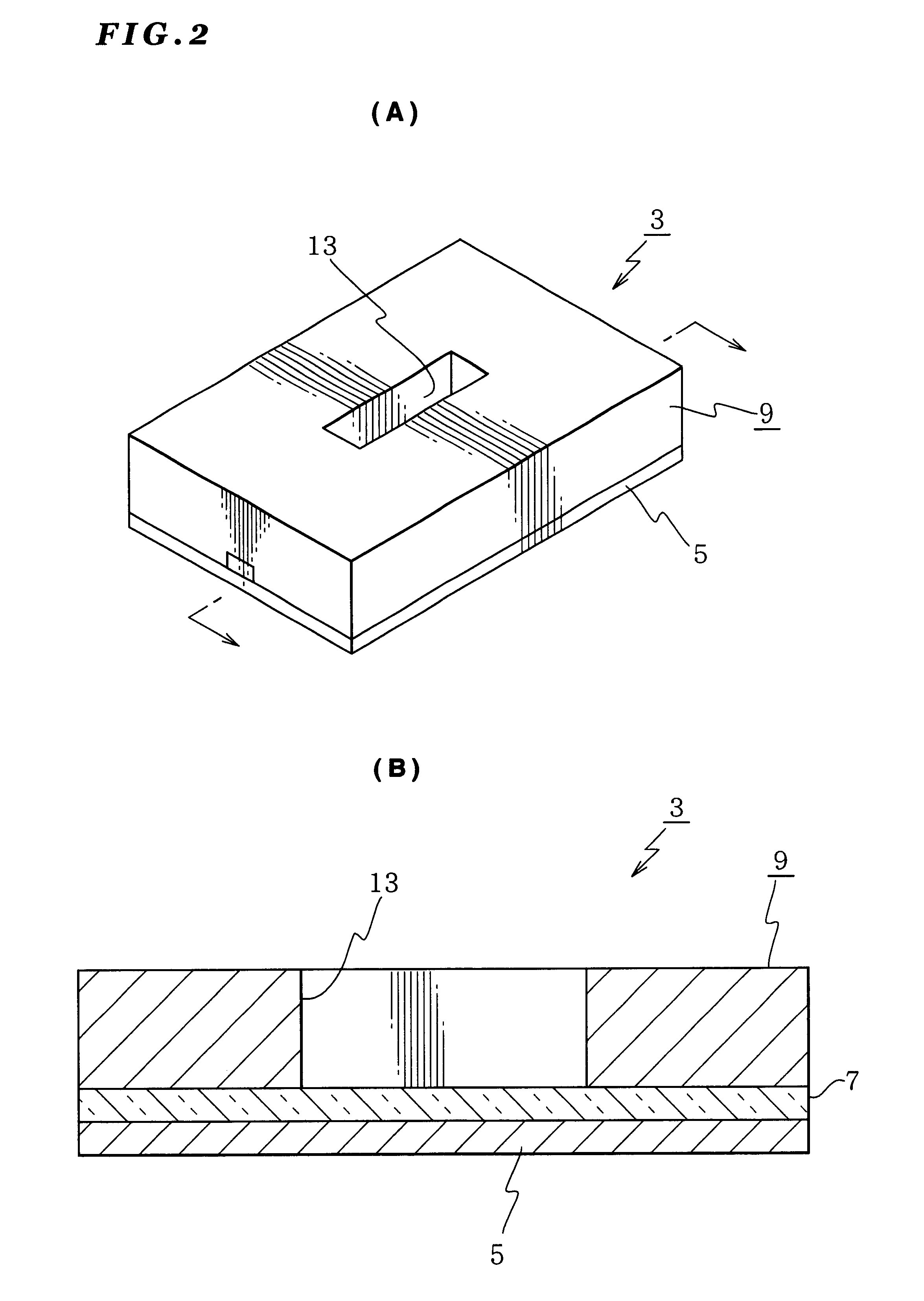
FIG. 59 is a perspective view of the SPR sensor according to The SPR sensor of this embodiment uses an optical waveguide (core). More specifically, the SPR sensor D3 is constituted by a sheet-shaped first clad (substrate) D5, a core D7 arranged on this first clad, and two intermediate clads D6 to sandwich this core D7 from both sides, and a second clad (upper plate) D9 to cover the core D7 and the intermediate clad D6. It should be noted that the optical waveguide may be planer type, strip type, embedded type, lens type, or the like.
The first clad D5 is made from glass or the like and formed into a thin sheet shape. The core D7 is placed on this first clad D5. The core extend over the entire length of the SPR sensor cell D3. This core is made from glass, plastic, or the like.
The core D7 may be attached to the first clad D5 using an adhesive or by way of heating for melting the boundary surfaces between the first clad D5 and core D7. The same applies to the mounting of the second cl...
modified example 1 of embodiment 24
Next, referring to FIG. 60, explanation will be given on a modified example of the SPR sensor cell. The sensor cell D3b differs from the SPR sensor cell of the aforementioned sensor cell in that two cores are used.
More specifically, this SPR sensor cell D3b is constituted by: a sheet-shaped first clad (substrate) D5, two cores D7a and D7b mounted on this first clad Dd5; a center clad D6b sandwiched by the cores D7a and D7b; side clads D6a to sandwich the two cores D7a and D7b from outside; and a second clad (upper plate) D9 to cover the cores D7a, D7b, the center clad D6b and the side clads D6a.
Moreover, the center clad D6b is divided into two blocks so as to define a void space between them. This void space corresponds to the predetermined through hole D13b formed at approximately center of the second clad D9. More specifically, the through hole extends from the upper surface of the second clad to the position defined by the two cores D7a and D7b. That is, the cores D7a and D7b are...
modified examples 2 and 3
of Embodiment 24
FIG. 61 is a perspective view of another modification of the SPR sensor cell according to Embodiment 24. The SPR sensor cell shown D3C shown in FIG. 61A has one core and the SPR sensor cell D3D shown in FIG. D61B has two cores. In these SPR sensor cells, surface treatment has been performed to the end surfaces excluding the end surface of the cores. More specifically, the first clad, the second clad, and intermediate clad have end surfaces subjected to surface treatment so that light cannot pass. The surface treatment may be obscuring by sandblast or the like, or coating with aluminum (Al) or applying a black paint.
When such a surface treatment has been performed, the light comes into only the cores D7 and D7a. If the light passes through the end surfaces of the clads, the light may come into the cores D7 and D7a, which may lower the immunoassay accuracy (sensitivity).
PUM
 Abstract
Description
Claims
Application Information