Method and apparatus for providing high contrast imaging
a high contrast imaging and high contrast technology, applied in the field of imaging analysis, can solve the problems of difficult vivo visualization of the circulation, limited resolution of such images, and particular problems of newborns,
- Summary
- Abstract
- Description
- Claims
- Application Information
AI Technical Summary
Benefits of technology
Problems solved by technology
Method used
Image
Examples
first embodiment
a. First Embodiment
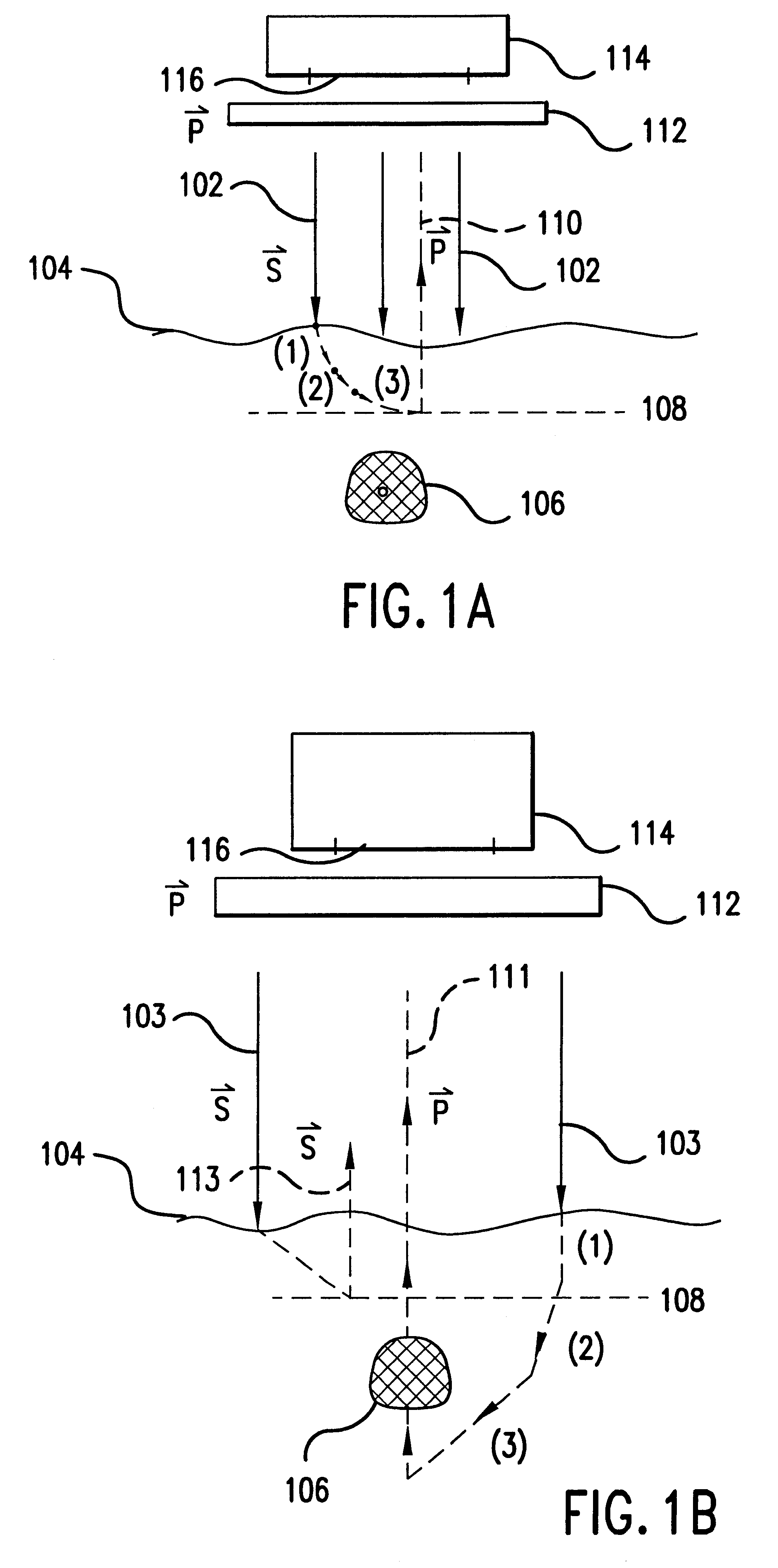
The first embodiment of the present invention is a device (or in vivo apparatus) that provides a high contrast illumination pattern that is projected onto a tissue region of a subject in order to provide an image of blood vessels, blood flow, or tissue contained therein. The in vivo apparatus comprises a light source, an illumination system, and an imaging system. The imaging system includes an imaging detector and its objective.
The illumination system provides an illumination beam that is used to illuminate a particular blood vessel or tissue area (referred to as the "object") of a patient or subject. The illumination beam propagates along a path or segment referred to as the illumination path. The detector receives light emanating from the object. This light is also referred to as the image beam. The path or segment that the image beam travels is referred to as the image path. According to the present invention, the in vivo apparatus can be designed so that the ...
second embodiment
b. Second Embodiment
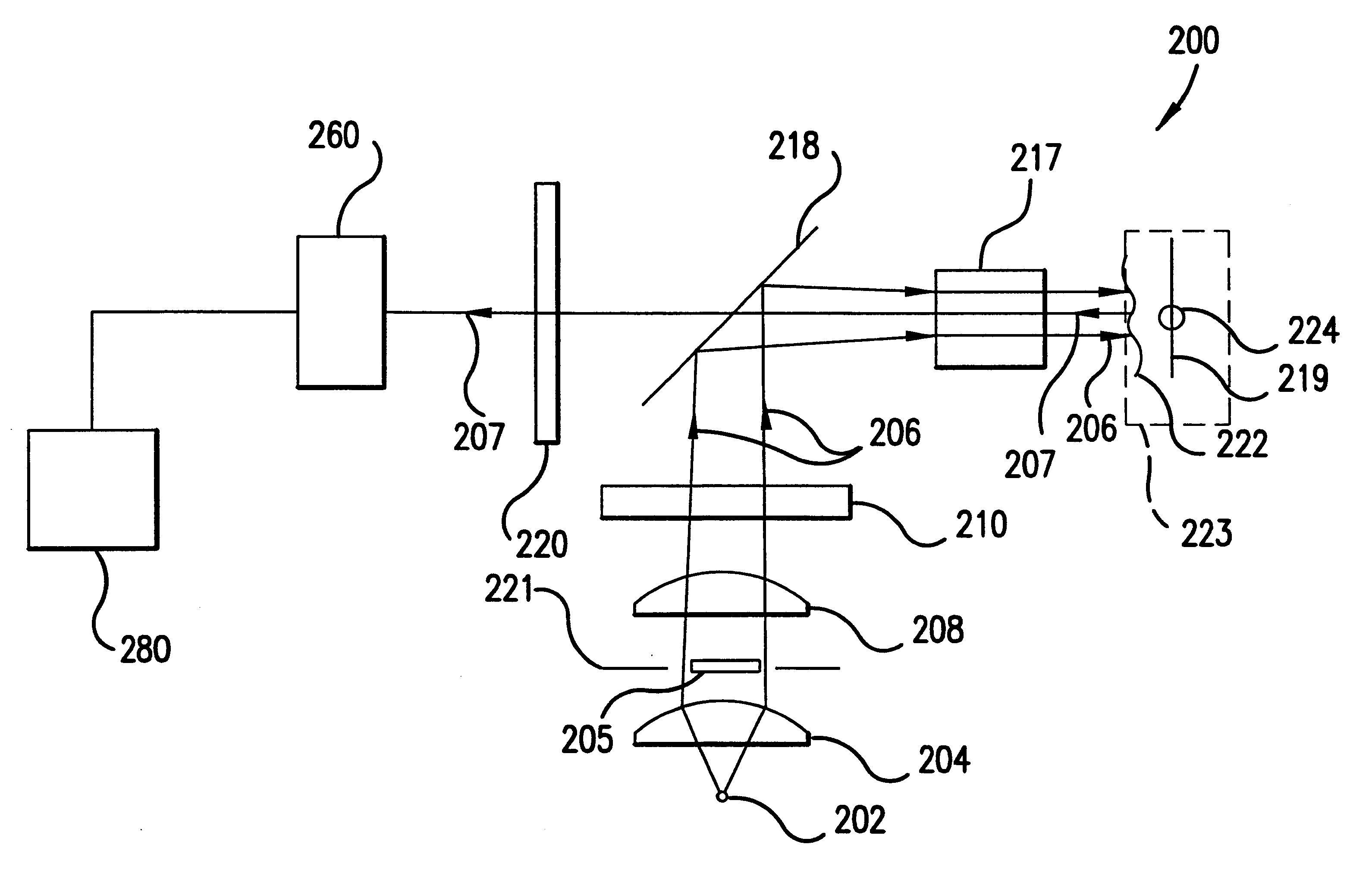
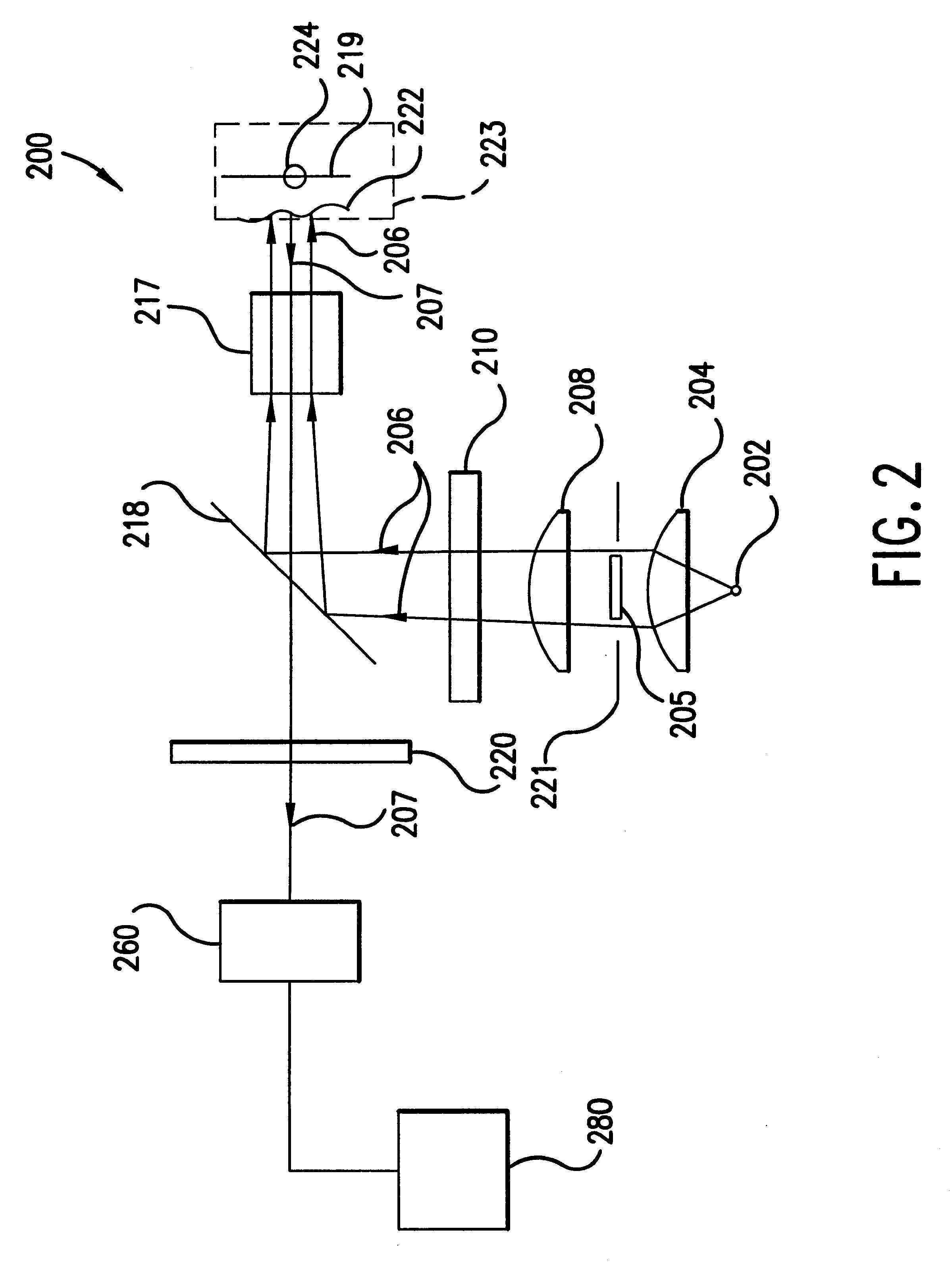
According to a second embodiment of the present invention, the illumination of the tissue region being viewed can be provided in a more efficient manner. For example, device 200 shown in FIG. 2 projects a high contrast illumination pattern onto the tissue region being viewed, thus providing a low rotational effect due to near field tissue birefringence. Yet, apparatus 200 requires a substantial amount of power from light source 202. High output intensity may be needed in order to provide enough illumination to saturate the annular ring outside the FOV of detector 260, which yields enough light into the limiting numerical aperture of the objective lens of the detector. A relatively higher amount of power is required because about 50% of the collimated illumination beam collected by collimating lens 204 is blocked off by obscuration 205.
For example, assume that illumination source 202 is a tungsten filament, which is a semi-lambertian emitter. Lambertian emitters h...
third embodiment
c. Third Embodiment
According to a third embodiment of the present invention, an imaging system comprises an improved folding mirror or beam splitter. Recall that in FIG. 2, a folding mirror or beam splitter 218 is used to redistribute light from the illumination system to the blood vessel, capillary, or tissue sample being imaged at the object plane. According to this embodiment, rather than using an obscuration or conical lens in combination with a standard 50% reflection / 50% transmission beam splitter, an improved folding mirror can transform the illumination beam and project a high contrast illumination pattern onto the object plane. The improved folding mirror or beam splitter can be designed as a mirror that has a completely transmissive center (i.e., having 100% transmission at the wavelength of the illumination and / or image beam). With this approach, a high contrast illumination pattern is imaged onto the object plane and nearly 100% of the intensity of the image beam that re...
PUM
| Property | Measurement | Unit |
|---|---|---|
| depths | aaaaa | aaaaa |
| focal length | aaaaa | aaaaa |
| diameter | aaaaa | aaaaa |
Abstract
Description
Claims
Application Information
 - R&D
- Intellectual Property
- Life Sciences
- Materials
- Tech Scout
- Unparalleled Data Quality
- Higher Quality Content
- 60% Fewer Hallucinations
Browse by: Latest US Patents, China's latest patents, Technical Efficacy Thesaurus, Application Domain, Technology Topic, Popular Technical Reports.
© 2025 PatSnap. All rights reserved.Legal|Privacy policy|Modern Slavery Act Transparency Statement|Sitemap|About US| Contact US: help@patsnap.com


