Circuit module for a phased array

a phased array and circuit module technology, applied in the direction of instruments, measurement devices, antennas, etc., can solve the problems of limited beam scan rate, bulky, costly and imperfect, and high cost of both antenna and servomotor

Inactive Publication Date: 2002-08-27
FLIR BELGIUM BVBA
View PDF16 Cites 57 Cited by
  • Summary
  • Abstract
  • Description
  • Claims
  • Application Information

AI Technical Summary

Problems solved by technology

Both antenna and servomotor are costly and cumbersome; the maximum beam scan rate is limited by the inertia and limited motor power of the antenna assembly.
They are bulky, costly and imperfect.
The development of phased array radars has been inhibited by the conflicting requirements of phase control and the need to increase radar frequency and power.
Moreover, the cost of electronic components suitable for the higher frequencies increases greatly and their availability deteriorates.
Silicon integrated circuits for example are unsuitable for use at GHz frequencies at which state of the art phased arrays are required to operate.
More than half of the area of the chip is devoted to the phase shifter, which is therefore responsible for a substantial proportion of the chip cost, failure rate and production faults.
Chips of this kind are characterised by very high cost and low yield.
However, direct digital synthesis suffers from the drawback that the highest frequencies that can be generated at present are more that a factor of ten below those required for a compact phased array radar.

Method used


Image

  • Circuit module for a phased array
  • Circuit module for a phased array
  • Circuit module for a phased array

Examples


Embodiment Construction

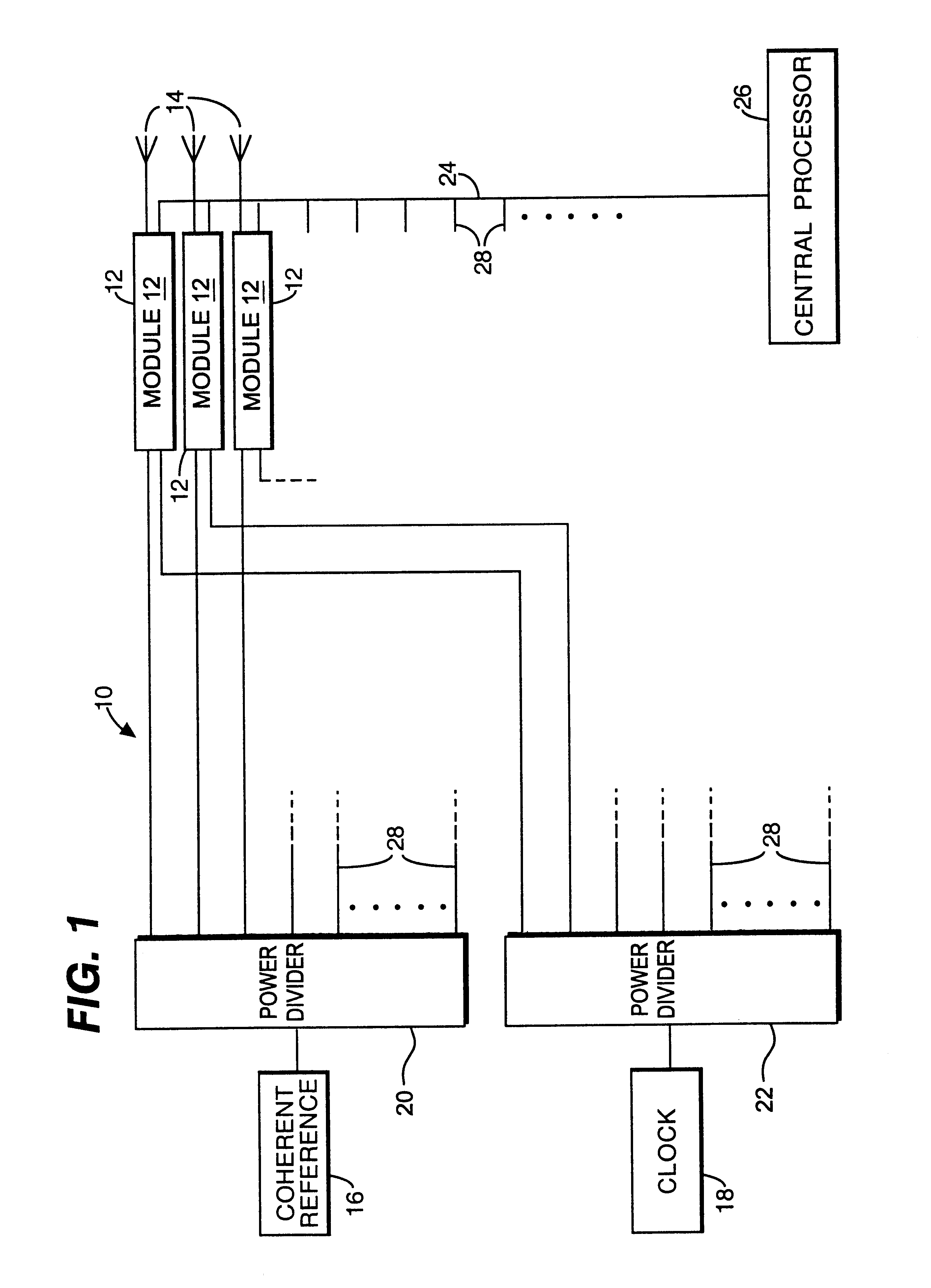
Referring to FIG. 1, there is shown a schematic block diagram of the electronic circuitry of a phased array radar device indicated generally by 10. The device 10 comprises a number of individual electronic modules 12 each with a respective antenna radiating element 14. The modules 12 and antennas 14 are of like construction, and in some embodiments each antenna 14 may be mounted on the circuit board (not shown) of its associated module 12. The antennas 14 (of which three are shown) are arranged to form a planar array.

A coherent reference signal generator 16 and a clock signal generator 18 are connected via respective power dividers 20 and 22 to each of the modules 12. Output signals from the modules 12 pass via a bus 24 to a central processor 26, ie a digital computer. Only three modules 12 are illustrated explicitly, but, as indicated by discontinuous connections such as 28, the device 10 incorporates a much larger number of modules.

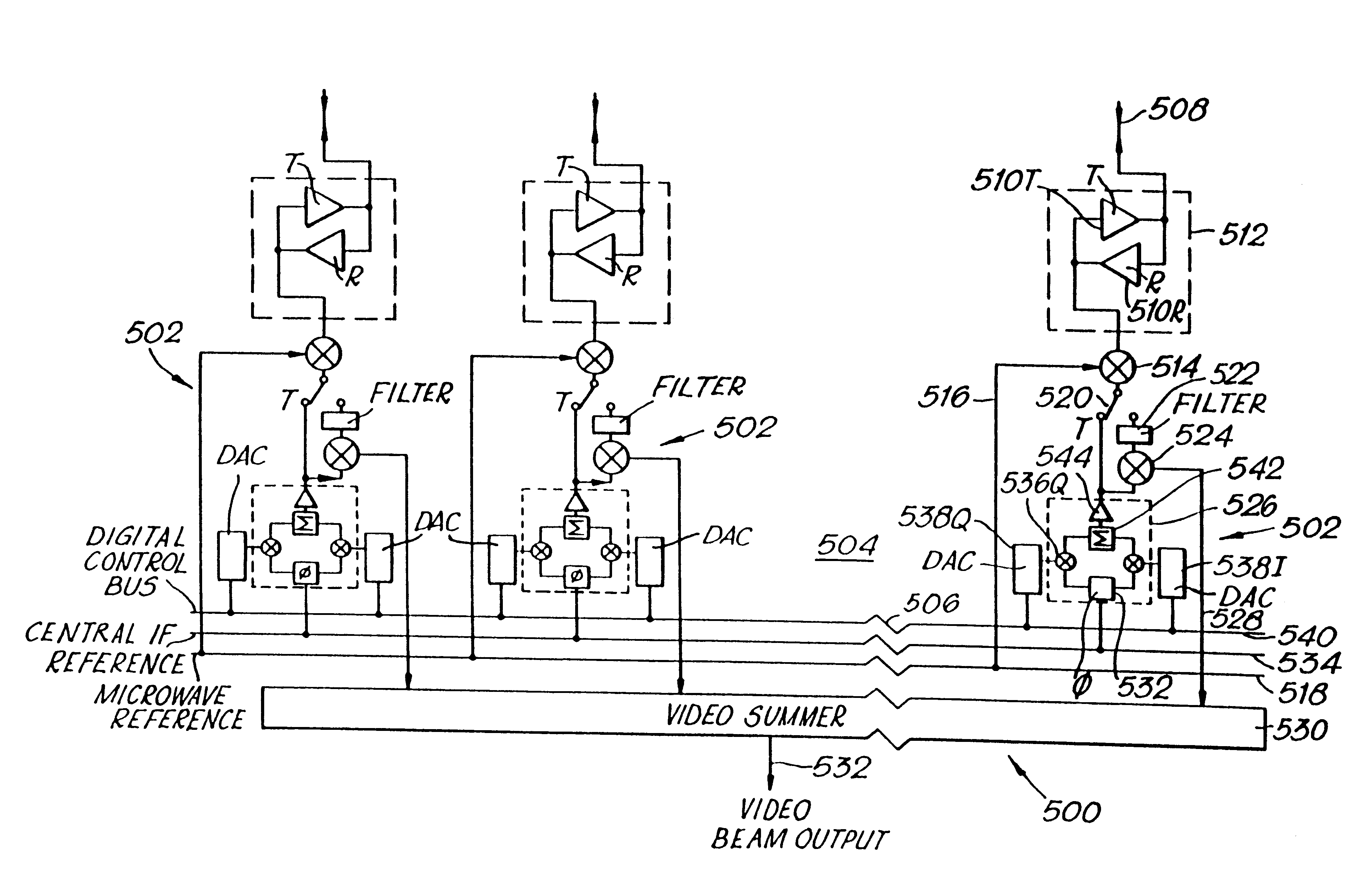
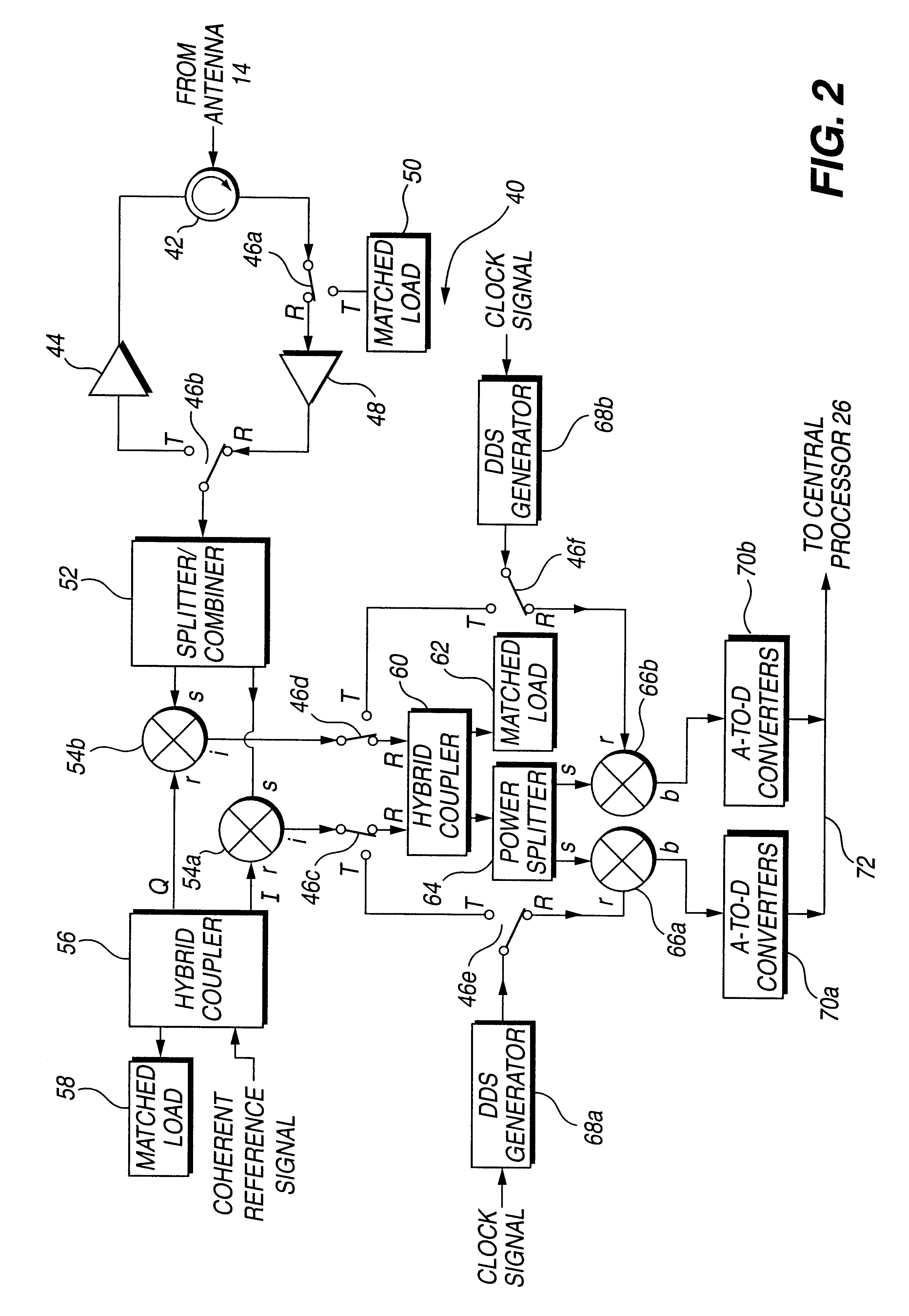
Referring now also to FIG. 2 and 3, there is show...


PUM


Abstract

A circuit module for a phased array (10) incorporates radio frequency (RF) mixers (54a, 54b) connected to an RF splitter/combiner (52) and to in-phase and quadrature RF reference signals. The RF mixers (54a, 54b) are also connected to intermediate frequency (IF) processing circuitry (60 to 68) providing for phase control of RF signals and IF reference signals. In transmission mode, the RF mixer (54a, 54b) receive phase-controlled, digitally synthesised IF signals from clock-activated generators (68a, 68b). Their outputs are combined at the RF splitter/combiner (52) to provide single sideband upconversion of the phase-controlled IF signals. In reception mode, the RF splitter/combiner (52) and the RF mixers (54a, 54b) act as an image rejection mixer circuit in which the phase-controlled IF signals are local oscillator signals. Beamforming is carried out by computer control of the IF phase together with, in the case of reception, analogue or digital summation of output signals from an array of modules (12).

Description

1. Field of the InventionThis invention relates to a circuit module for a phased array.2. Discussion of Prior ArtPhased arrays have been under development for over twenty years to overcome the problems of mechanically scanned radars. An example of the latter typically employs a reflecting dish antenna rotated by a servomotor. Both antenna and servomotor are costly and cumbersome; the maximum beam scan rate is limited by the inertia and limited motor power of the antenna assembly.In a phased array radar system, beamsteering or beamforming, ie control of the radar transmission or reception direction, is electronic instead of mechanical. Such a system consists of an array of antenna elements each connected to radar signal generation and reception circuitry. Each antenna element radiates when supplied with radar frequency (RF) power, and responds to incident radiation of appropriate frequency by producing a received signal. Received signals are downconverted to intermediate frequency (I...

Claims


Application Information

Patent Timeline
Patent Type & Authority Patents(United States)
IPC IPC(8): G01S7/03G01S7/28G01S7/282
CPCG01S7/032G01S7/282H04Q2213/13003G01S2007/4073G01S7/4073
Inventor DEAN, MICHAEL
Owner FLIR BELGIUM BVBA
Why Eureka
Try Eureka