

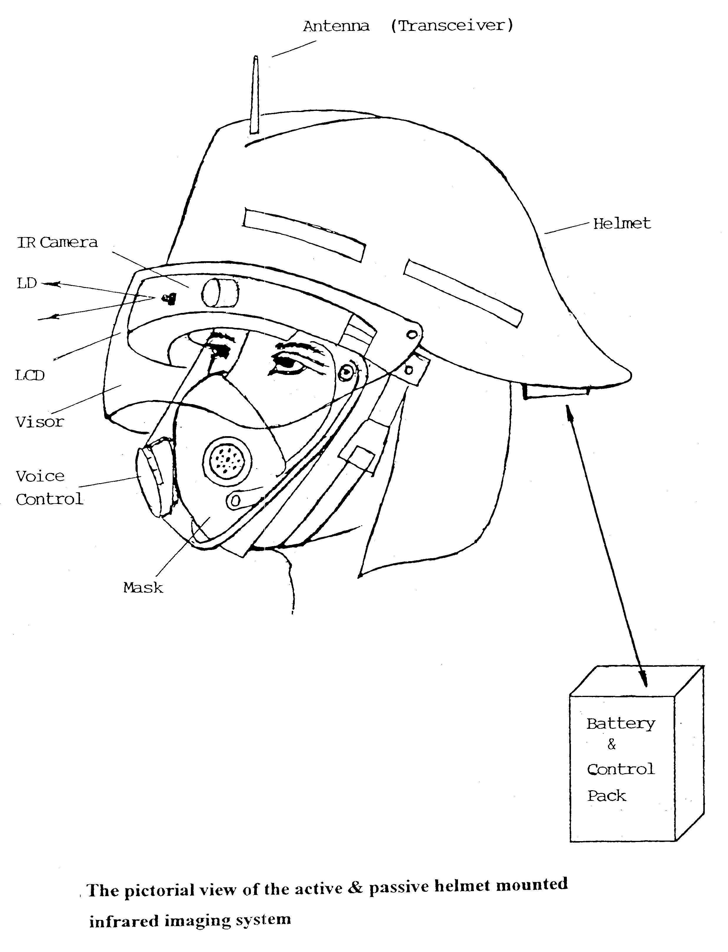
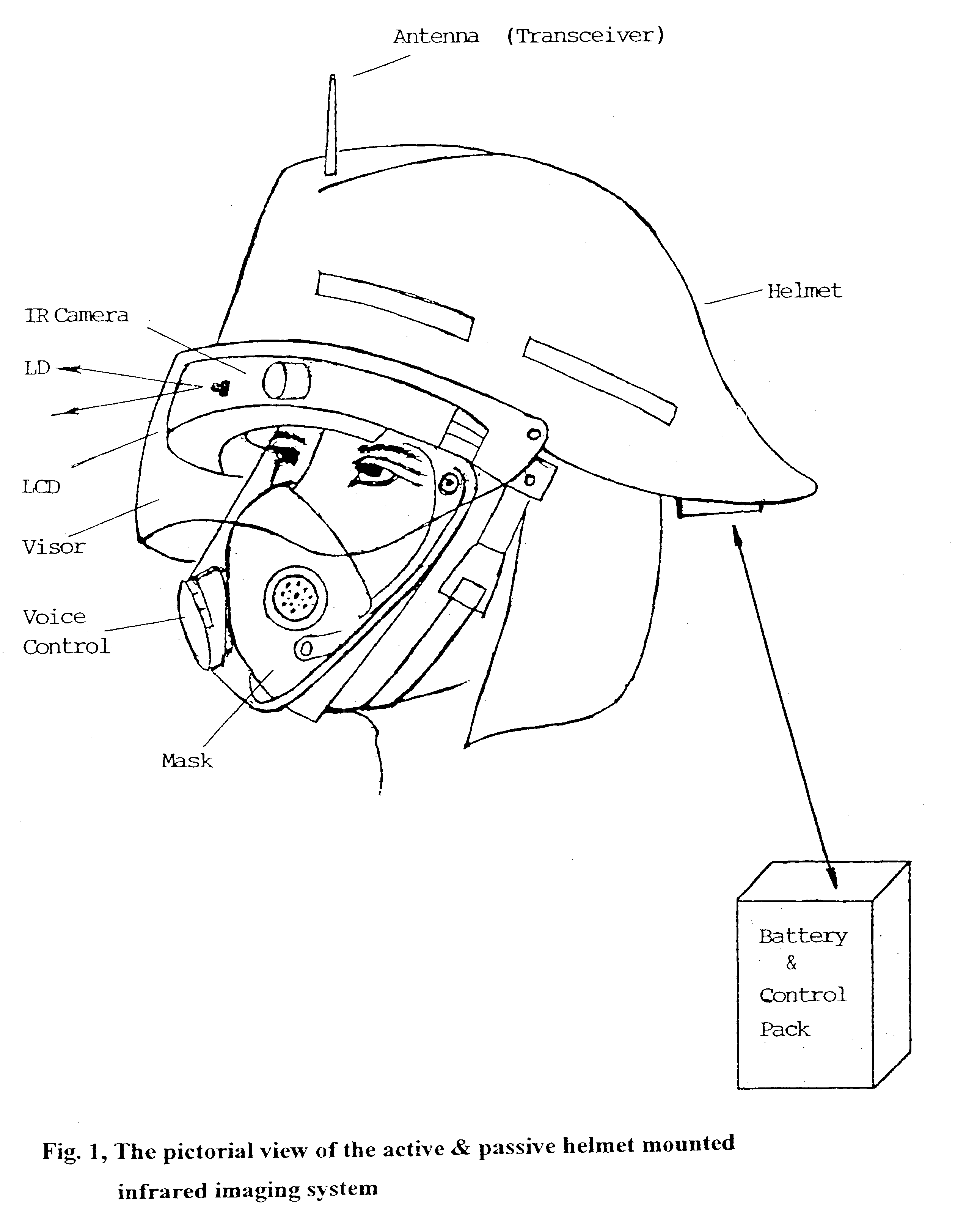
Head/helmet mounted passive and active infrared imaging system with/without parallax
a head/helmet technology, applied in the field of head/helmet mounted passive and active infrared imaging systems, can solve the problems of unrivalled manoeuvrability, limited thermal insulation level of the sensor, and high cost restriction of applications
- Summary
- Abstract
- Description
- Claims
- Application Information
AI Technical Summary
Problems solved by technology
Method used
Image

Examples
Embodiment Construction
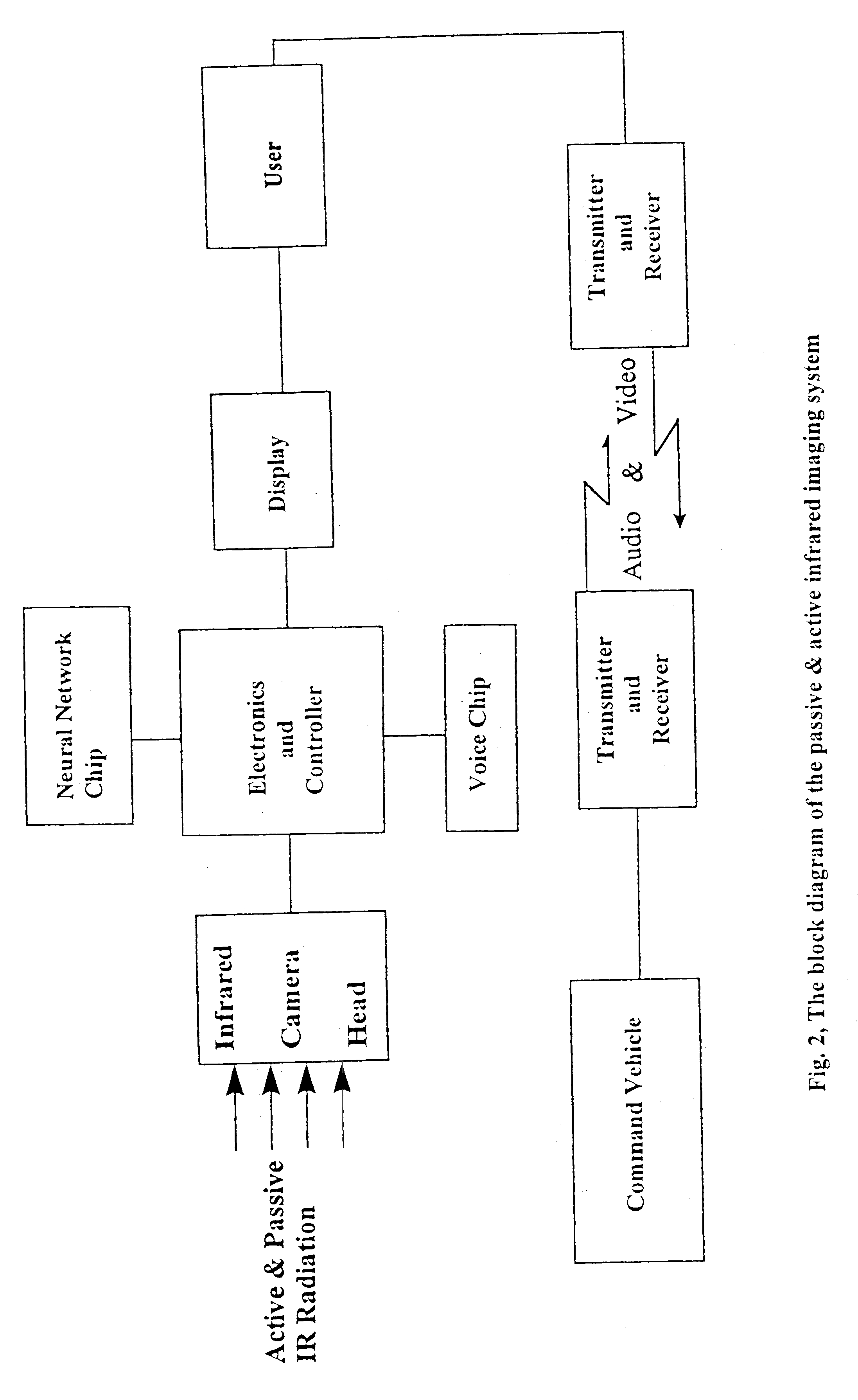
As shown in FIG. 3, Infrared radiation 10 from the target is collected by the Non-Ge (or Ge) objective lens 20 and sent to the Uncooled Focal Plane Array (UFPA) 30. The UFPA has pixels of n columns and m rows. Its readout circuit is a silicon integrated circuit which has following functions: (a) detector sense amplifier (one per pixel), (b) column multiplexer switch (one per column), (c) column amplifier (one per column), and (d) row multiplexer switch (one per row). Therefore, the parallel optical input becomes serial electronic output. After pre-processing of the UFPA signal and converting the Analog data to Digital (A / D) by the Focal Plane Array Interface Board 40, the signal goes to the main processing board--Video Controller Board 45 having software written on the EPROM. A Voice Activated Switching (or Command) Chip 60 and a Pattern Recognition Chip 65 are linked with the Video Board to help the signal processing. The output of the Video board after D / A converter becomes analog...
PUM
 Abstract
Description
Claims
Application Information