Test, reset and communications operations in an ARC fault circuit interrupter with optional memory and/or backup power

a technology of arc fault circuit interrupter and optional memory, applied in the integration of power network operation system, emergency protective arrangement for limiting excess voltage/current, sustainable buildings, etc., can solve problems such as "ticking faults", circuit breakers interrupting electric circuits, and conventional circuit breakers tripping, etc., to achieve reliable detection of arc fault conditions

Inactive Publication Date: 2002-09-24
SQUARE D CO
View PDF33 Cites 93 Cited by
  • Summary
  • Abstract
  • Description
  • Claims
  • Application Information

AI Technical Summary

Benefits of technology

It is a general object of the present invention to provide an improvement in an arc fault interrupter system which reliably detects arc fault conditions which may be ignored by conventional circuit interrupters.

Problems solved by technology

Typically, circuit breakers interrupt an electric circuit due to a disconnect or trip condition such as a current overload or ground fault.
A ground fault trip condition is created by an imbalance of currents flowing between a line conductor and a neutral conductor which could be caused by a leakage current or an arcing fault to ground.
However, arcing faults may not cause a conventional circuit breaker to trip.
Occasionally, however, the arc blows apart the faulted components creating a larger arc voltage and reducing the fault current below the trip curve and causing "ticking faults."
The average current may not be sufficient to trip a conventional breaker by heating the bimetal strip or the peak current may not be large enough to trigger the magnetic trip latch.
Unfortunately, the fault current can be limited by a circuit with too much impedance to immediately trip the thermal-magnetic breaker.
Parallel arcing is generally more hazardous than series arcing.
The energy released in the arc is much higher with temperatures often in excess of 10,000 Deg. F. This causes pyrolyzation or charring of the insulation, creating conductive carbon paths and ejecting hot metal that can encounter flammable materials.
Since the peak current is typically never greater than the design load current, series arcing is much more difficult to detect than parallel arcing.
These arcs cause load voltage drops and heating of the wire, plug pin, or terminal lug.
This heating can lead to component failure and ignition sources.
There are many conditions that may cause an arcing fault.
For example, corroded, worn or aged wiring, connectors, contacts or insulation, loose connections, wiring damaged by nails or staples through the insulation, and electrical stress caused by repeated overloading, lightning strikes, etc.
These faults may damage the conductor insulation and cause the conductor to reach an unacceptable temperature.
Standard overcurrent devices used in circuit breakers respond to the heating effect of current in a resistive wire to "thermal trip" the breaker, but these do not respond to the sputtering arc currents.
Until recently, such arc detection capability has not been available in circuit breakers or relays.
Under ideal conditions, GFCI can detect phase to ground arcs as low as six milliamps, but cannot detect series arcs or improve line to neutral fault trip times.
During arcing faults these currents are often small, short in duration and well below the over current time protection curve designed into these breakers.
Summarizing briefly, heat, arcs or electrical ignition are often caused by loose connections, broken or shorted wires in the power distribution system.
In wiring, vibration, moisture temperature extremes, improper maintenance and repair all contribute to wiring failure.
This leads to arcing and may ignite combustible components.
Furthermore, carbon tracking caused by heat generated by the arc can deteriorate the wire insulation, exposing the conductors and resulting in intermittent short circuits between individual wires.
These inter-wire shorts can cause damage and malfunctions.

Method used


Image

  • Test, reset and communications operations in an ARC fault circuit interrupter with optional memory and/or backup power
  • Test, reset and communications operations in an ARC fault circuit interrupter with optional memory and/or backup power
  • Test, reset and communications operations in an ARC fault circuit interrupter with optional memory and/or backup power

Examples


Embodiment Construction

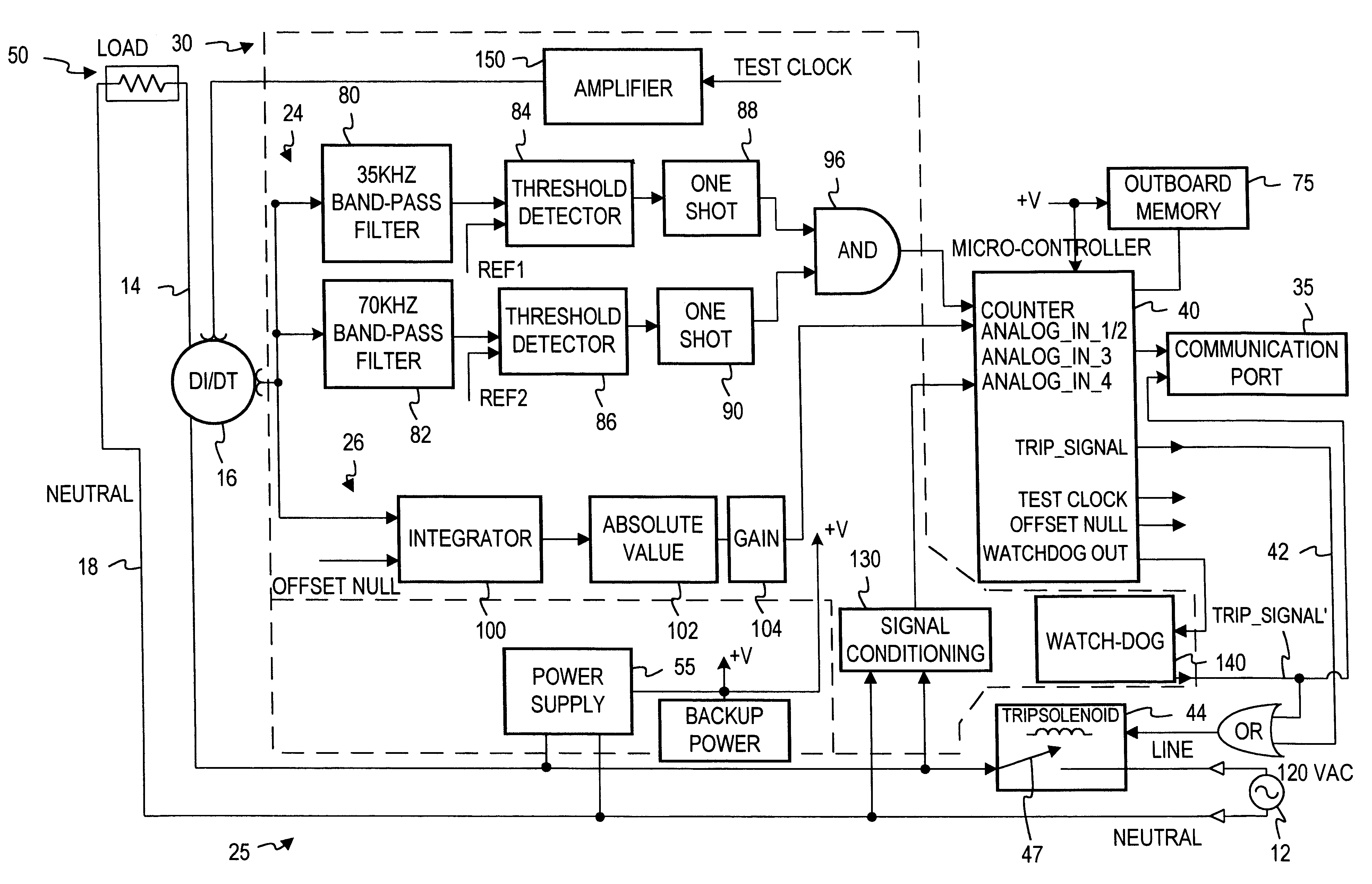
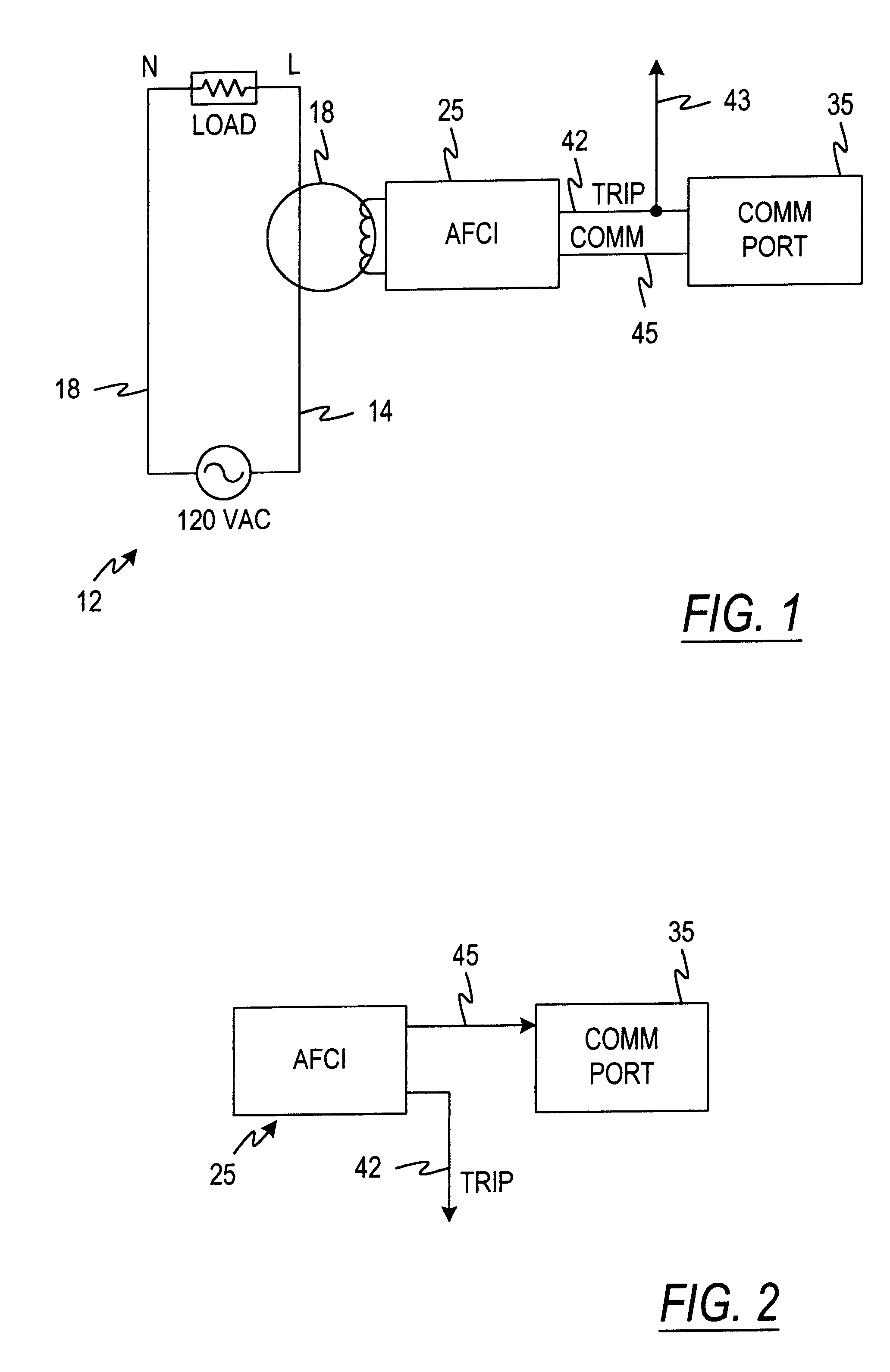
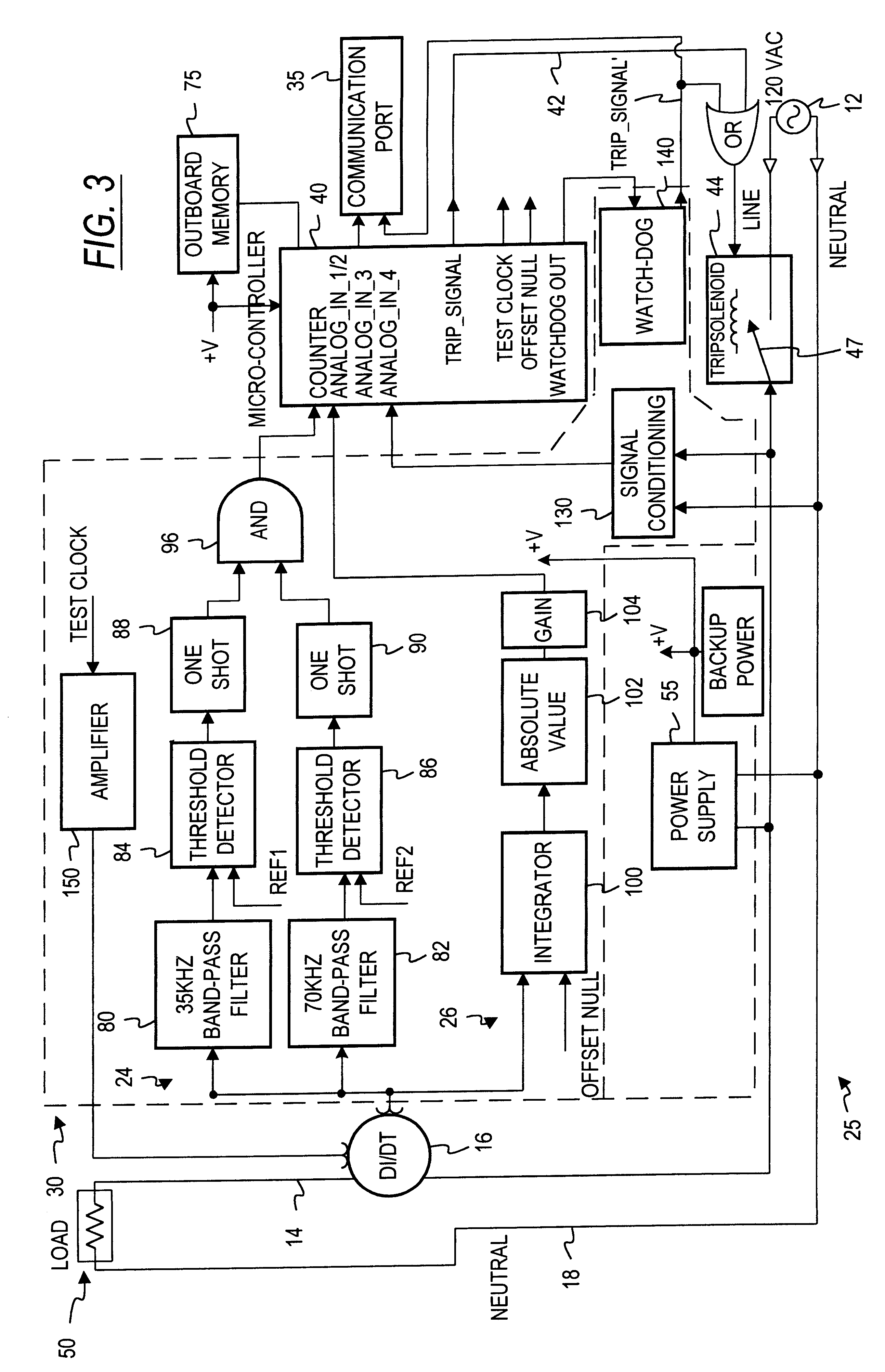
Referring now to the drawings and initially to FIG. 1, an arcing fault detection system in accordance with one embodiment of the invention is illustrated in functional block form. A 120 volt AC circuit 12 has a line conductor 14 and a neutral conductor 18. A sensor 16, which may be in the form of a di / dt coil is associated with the line conductor 14 and feeds an output signal to an arcing fault detection circuit or arc fault circuit interrupter (AFCI) 25. The AFCI circuit 25 has respective trip 42 and communications 45 outputs which are coupled with a communications port 35. The trip output 42 may also be coupled to directly or indirectly activate or trip a circuit interruption device for interrupting the current flow in the 120 VAC circuit 12 when an arcing fault is detected, as indicated by reference numeral 43.

The communication port 35, as shown in FIG. 2, may alternately receive only the communications signals from the AFCI 25 in which case the communications line 45, in additio...


PUM


Abstract

An arc fault circuit interrupter system for use with an electrical circuit includes an arcing fault detector which monitors the electrical circuit and a controller which generates a trip signal in response to the detection of arcing faults. The controller may also generate one or more communication signals corresponding to information relating to the operation of the arcing fault circuit interrupter. The system may also include one or more of the following: a communication port which communicates to a user the information relating to operation of the arc fault circuit interrupter in response to the communication signals; a memory for retaining predetermined information related to the condition and operation of the arcing fault circuit interrupter, with or without a backup memory; and a combined self-test/reset switch.

Description

The present invention relates to the protection of electrical circuits and, more particularly, to the detection of electrical faults of the type known as arcing faults in an electrical circuit and more particularly still to test, reset and communications operations in an arc fault circuit interrupter with memory and / or backup powerThe electrical systems in residential, commercial and industrial applications usually include a panel board for receiving electrical power from a utility source. The power is then routed through protection devices to designated branch circuits supplying one or more loads. These overcurrent devices are typically circuit interrupters such as circuit breakers and fuses which are designed to interrupt the electrical current if the limits of the conductors supplying the loads are surpassed.Circuit breakers are a preferred type of circuit interrupter because a resetting mechanism allows their reuse. Typically, circuit breakers interrupt an electric circuit due t...

Claims


Application Information

Patent Timeline
Patent Type & Authority Patents(United States)
IPC IPC(8): H01H71/12H02H1/00H02H3/44H02H3/08H02H1/06H02H3/10
CPCH01H71/125H02H1/0015H01H71/128H01H2083/201H01H2300/03H02H1/06H02H3/105H02H3/44Y02B90/224Y04S20/14Y02B70/3241Y04S20/227Y02B90/20H02H3/04Y02B70/30Y04S20/20
Inventor HAUN, ANDY A.GRATTAN, BRIAN G.WONG, KON B.DVORAK, ROBERT F.SCOTT, GARY W.
Owner SQUARE D CO
Why Eureka
Try Eureka