
Method of making clad materials using lead alloys and composite strips made by such method

a technology of lead alloys and composite strips, applied in the direction of cell components, soldering devices, manufacturing tools, etc., can solve the problems of limiting the range and the usefulness of electric and hybrid vehicles, such batteries, and their bulky size and heavy weight, and achieve the difficulty of manufacturing composite plates and grids

Inactive Publication Date: 2002-11-05
EMS ENGINEERED MATERIALS SOLUTIONS LLC
View PDF14 Cites 7 Cited by
  • Summary
  • Abstract
  • Description
  • Claims
  • Application Information

AI Technical Summary

Benefits of technology

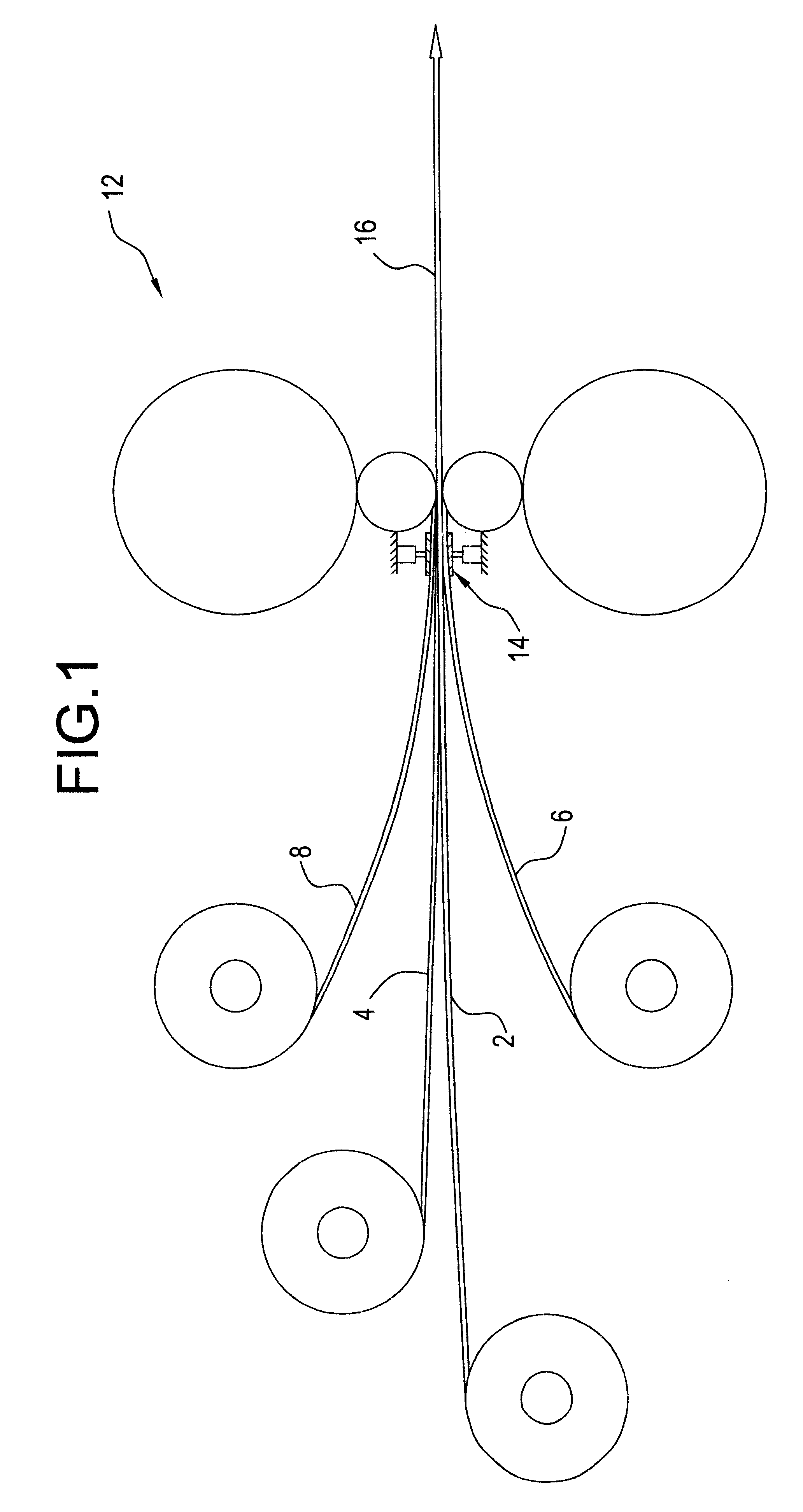
According to a feature of the invention the differences in physical properties between the core layer and the outer lead or lead alloy layers, particularly yield strength, is minimized by softening the core material, as by annealing, and by strengthening the lead or lead alloy layers by the addition of a minor amount of calcium or antimony, more specifically, less than 1% by weight. According to another feature of the invention, the amount of tension applied to the several layers going into the roll mill may be adjusted to control the specific thickness ratios of the several layers to one another. According to yet another feature of the invention, conventional lubrication of the bonding rolls is eschewed with the bonding rolls being maintained in a dry condition.

Problems solved by technology

The disadvantages of such batteries are their bulky size and heavy weight.
This limits the range and the usefulness of vehicles, both electric and hybrid, using such batteries.
The biggest barriers to the commercialization of the bi-polar lead / acid batteries are the technical difficulties of manufacturing the composite plates and the difficulty of producing the grids.
This preliminary deposition not only is time consuming but it adds undesirable cost.

Method used


Image

  • Method of making clad materials using lead alloys and composite strips made by such method
  • Method of making clad materials using lead alloys and composite strips made by such method
  • Method of making clad materials using lead alloys and composite strips made by such method

Examples


example i

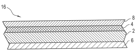
It A continuous strip 2a of fully annealed CP (commercially pure) titanium (Grade 50A) having a nominal thickness of 0.021 of an inch was thoroughly cleaned and scratch brushed. Two continuous strips 4a, 6a of fully age hardened lead alloy, each of nominal chemical composition of lead -0.06% calcium-1.5% tin, and each having a nominal thickness of 0.015 of an inch were cleaned by vapor degreasing. The cleaned and brushed CP titanium was sandwiched between top and bottom layers of lead alloy and then rolled on a conventional roll bonding mill having essentially dry bonding rolls in one pass with sufficient force to reduce the sandwich package thickness from about 0.051 of an inch to about 0.023 of an inch. i.e., a reduction of about 54% and using minimal tension on the separate layers. A sample of the; roll bonded composite material thus produced is shown in FIG. 10, a micro-photograph of a cross section of the roll bonded tri-clad composite comprising lead alloy 4a / CP titanium 2a / le...

example ii

The same process as described in Example I except that the core layer 2b was fully annealed SAE 304 stainless steel having a thickness of 0.036 of an inch. In the roll bonding operation the initial'sandwich thickness of about 0.066 of an inch was reduced to a roll bonded thickness of about 0.030 of an inch, i.e., about 55% reduction. FIG. 12 shows a cross sectional micro-photograph of the tri-clad lead alloy 4a / 304ss 2b / lead alloy 6a showing the establishment of a continuous solid state bond at the lead and the stainless steel interfaces.

example iii

This example was carried out in the same manner as in Example I except that the core layer used was fully annealed SAE 1008 low carbon steel (LCS) having a thickness of 0.038 of an inch. In the roll bonding operation the initial sandwich thickness of about 0.068 of an inch was reduced to a bonded thickness of about 0.028 of an inch, i.e., about 59% reduction. FIG. 13 shows a cross sectional micro-photograph of the tri-clad lead alloy 4a / 1008LCS 2c / lead alloy 6a showing the establishment of a continuous solid state bond at the lead and the 1008LCS interfaces.


PUM

PropertyMeasurementUnit
speedaaaaaaaaaa
rolling speedaaaaaaaaaa
thicknessaaaaaaaaaa

Abstract

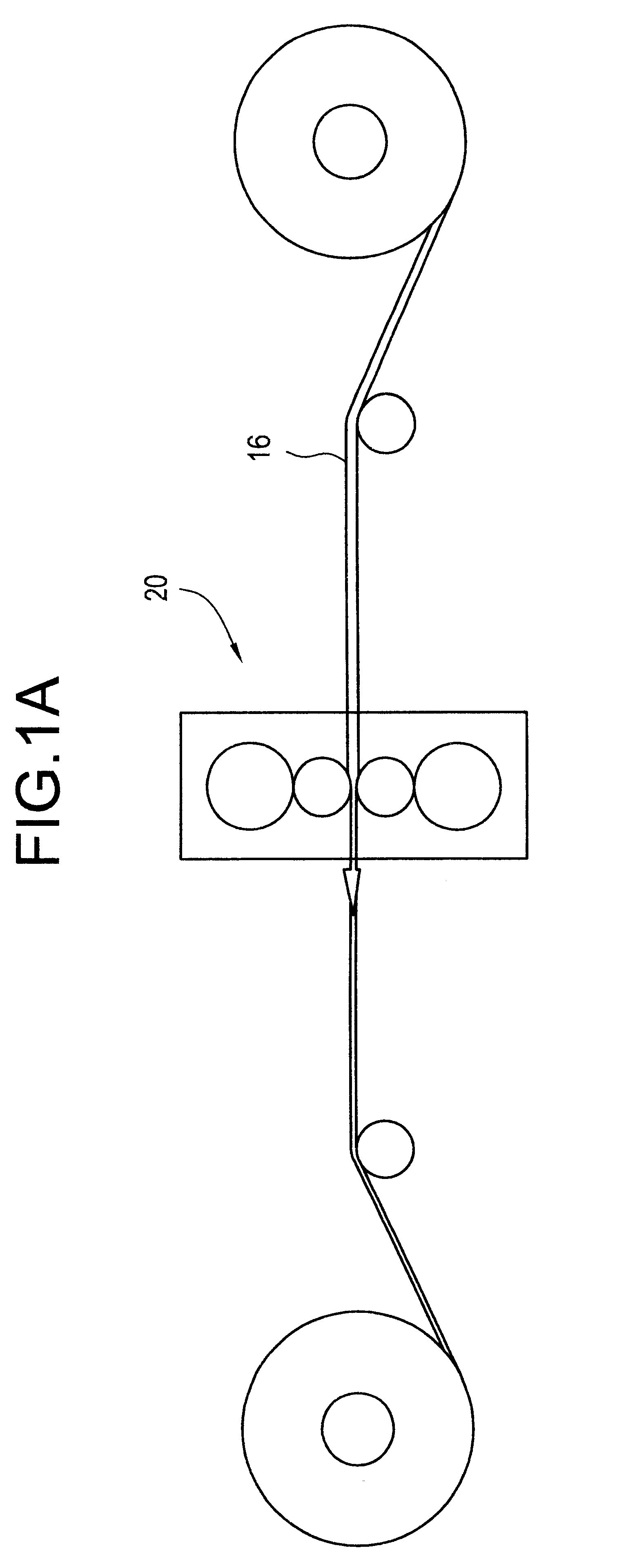
Lead alloy strip material (4, 6, 8) is roll bonded on one or both opposite face surfaces of a core strip material (2). The core material can be commercially pure titanium, austenitic stainless steel, low carbon steel, copper, aluminum, alloys thereof or other suitable metal that has sufficient ductility and that can provide desired attributes of stiffness and corrosion resistance to the composite. The lead alloy material is strengthened by the addition of less than approximately 1% of calcium or antimony and the core material is softened by fully annealing it prior to bonding. The several strips are reduced in thickness, preferably in approximately the same proportion, by at least 40% in the bonding pass to create a solid phase bond among the strips. The bonded composite is then rolled to final gauge and, for selected applications, is corrugated and cut to form panels (20, 22, 24) and etched to form pockets (8b) for pasting of active materials such as lead oxide for battery plates.

Description

1. FIELD OF THE INVENTIONThis invention relates generally to the solid phase bonding of metals, that is, the bonding of metals without the formation of any liquid phase material at the interface of the metals being bonded, and more particularly to methods for solid phase bonding one or more layers of a lead alloy and a core layer of other metal having a selected attribute of stiffness.2. BACKGROUND OF THE INVENTIONComposites formed of a core of titanium, austenitic stainless steel, low carbon steel, copper, aluminum or other material having suitable ductility and which can provide desired attributes of stiffness and corrosion resistance to the composite, and outer layers of lead alloys are particularly useful for various applications including batteries, ducting, x-ray shielding, chemical plants and sound attenuation. One application of particular interest is that of battery plates for lead-acid batteries.Electric and hybrid vehicles (i.e., vehicles having auxiliary power sources su...

Claims


Application Information

Patent Timeline
Patent Type & Authority Patents(United States)
IPC IPC(8): B23K20/04B23K35/00B32B15/01C22C11/06C22C11/00H01M4/66H01M4/82H01M4/68H01M4/64H01M4/02H01M4/70H01M4/14H01M10/18
CPCB23K20/04B23K35/001B32B15/01C22C11/06H01M4/82H01M4/685Y10T428/12701H01M4/70H01M2004/029Y02E60/126Y02E60/10
Inventor PANDEY, AWADH K.JHA, BIJENDRA
Owner EMS ENGINEERED MATERIALS SOLUTIONS LLC
Learn More