Two dimensional object position sensor

a two-dimensional object and position sensor technology, applied in the direction of counting objects on conveyors, using reradiation, instruments, etc., can solve the problems of uneconomical and impractical options, pinpointing the exact location, and small area imaging arrays to sense the position of objects over a large area

Inactive Publication Date: 2002-11-05
XEROX CORP
View PDF1 Cites 265 Cited by
  • Summary
  • Abstract
  • Description
  • Claims
  • Application Information

AI Technical Summary

Problems solved by technology

Due to the small pixel size and the technology that underlies the small area imaging arrays using such imaging arrays to sense the position of an object over a large area is impractical, especially when the object is in the near field of these small area imaging arrays.
In addition, the sheet of paper may only positively be located within the paper path when it passes by one of these position sensors and is unaccounted at all other positions within the paper path.
Because of this, it may often be difficult, for example, to pinpoint the exact location of a paper sheet that has become jammed in the paper path.
In such conventional photocopiers and printers, these position sensors are often only capable of sensing a sheet of paper in one dimension.
While this may provide improved tracking of a sheet of paper throughout the paper path, it is an option that is currently uneconomical and impractical.

Method used


Image

  • Two dimensional object position sensor
  • Two dimensional object position sensor
  • Two dimensional object position sensor

Examples


Embodiment Construction

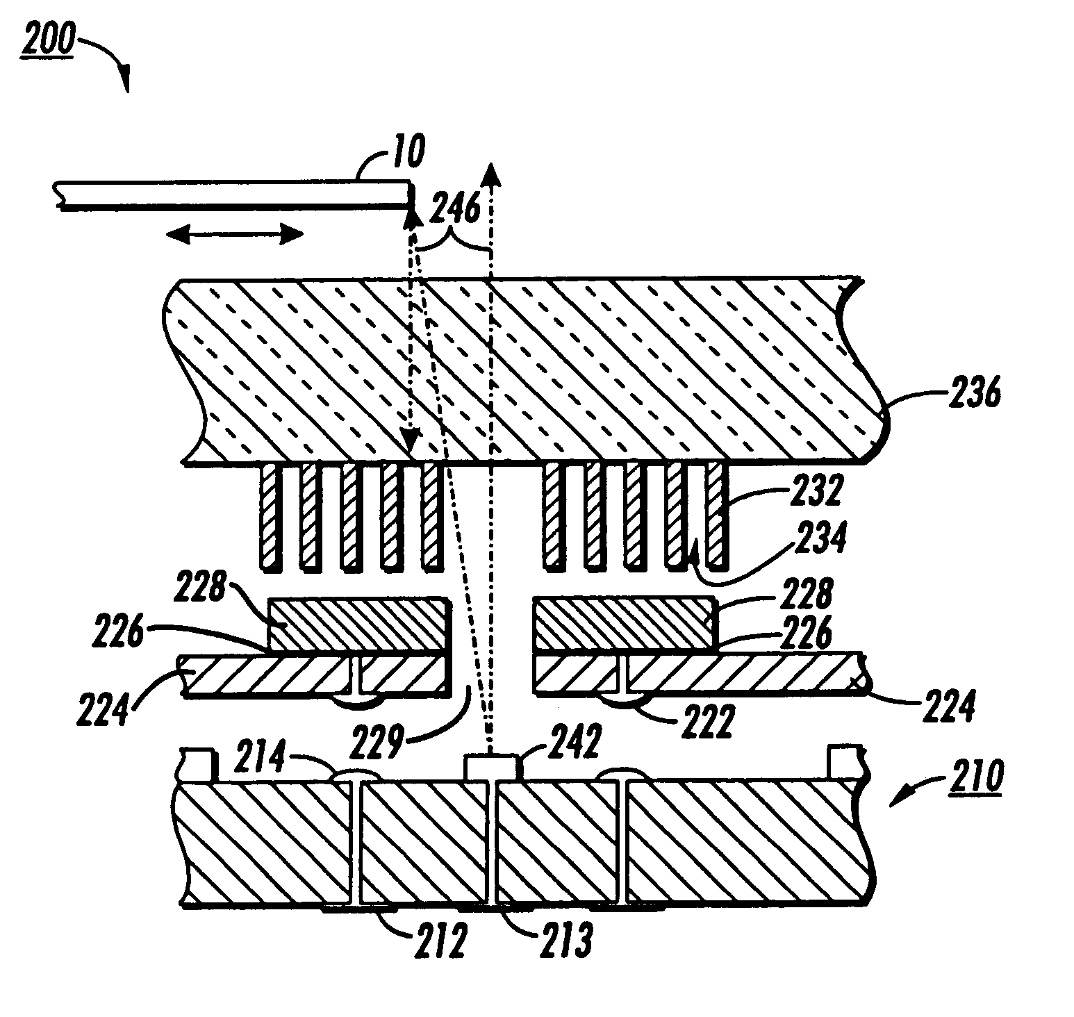
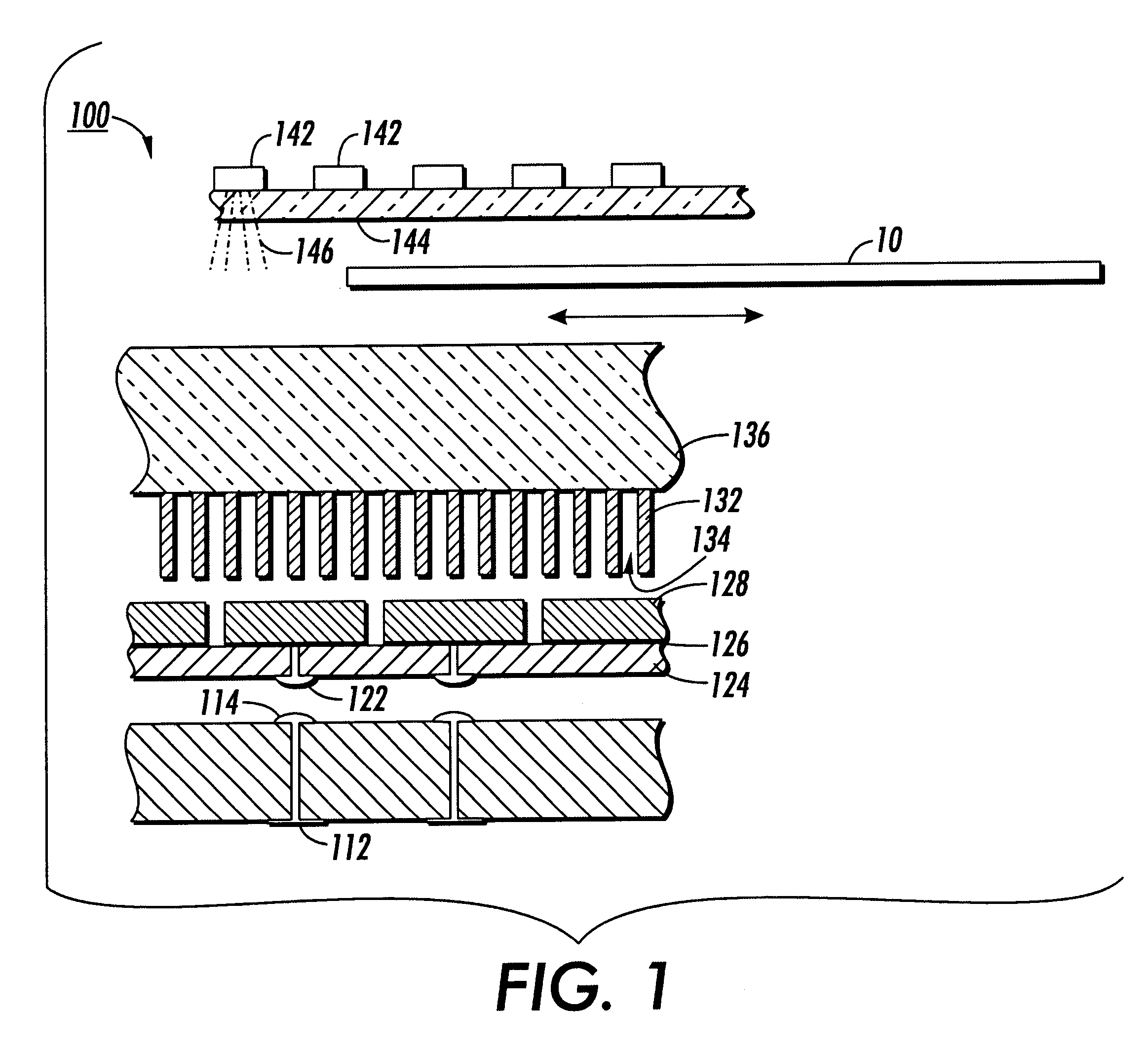
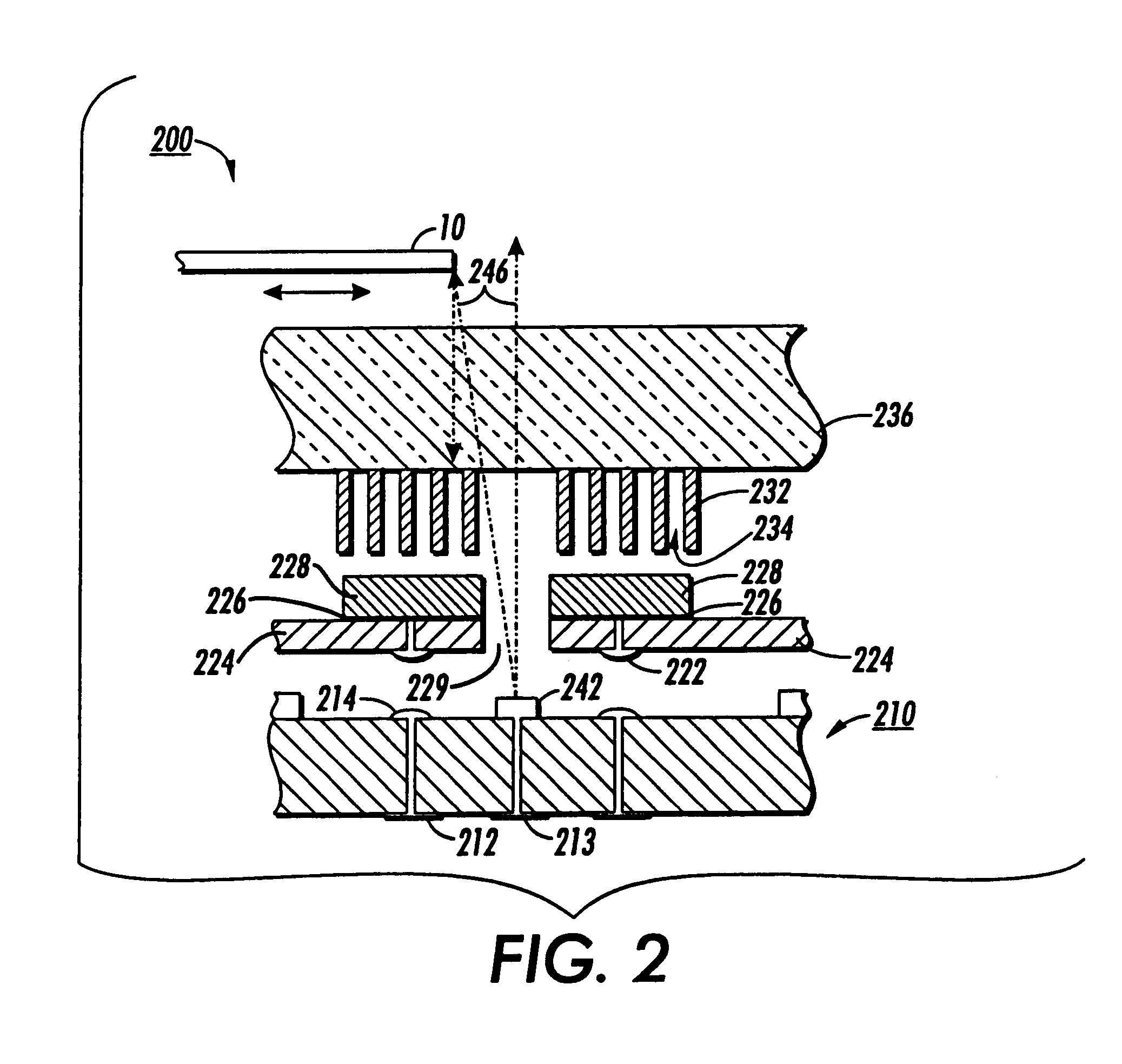
FIG. 1 shows a first exemplary embodiment of a large area object position sensor 100 according to this invention. As shown in FIG. 1 the large area object position sensor 100 includes a number of light sources 142 mounted on a transmissive plate 144. The light sources 142 emit light energy 146 towards a transmissive plate 136. An object 10 passing between the transmissive plate 144 and the transmissive plate 136 will block the light energy 146 from reaching the transmissive plate 136. The light sources 142 may be any known or later-developed type of light emitting device, including, but not limited to, infrared light emitting diodes, light emitting diodes, or ordinary light bulbs. As shown in FIG. 1, the transmissive plate 144 may be formed from a rigid material and thus may act as a substrate for mounting the light sources 142. Both the transmissive plate 136 and the transmissive plate 144 may be formed of plastic and / or glass materials and may be rigid or flexible. The object 10 m...


PUM


Abstract

Apparatus and method for sensing the position, size, shape and location orientation of one or more objects in two dimensions. The position sensor uses arrays of light sensors mounted on a substrate. When an object passes in proximity to the light sensors light energy from a plurality of light sources is either reflected from the object to the light sensors, or is emitted directly to the light sensors. The light energy is then converted to individual signals and transmitted through circuit traces in a printed circuit board to a local controller. The information may then be processed to determine the size, position, shape and location orientation of an object.

Description

1. Field of InventionThis invention relates to a two-dimensional object position sensor usable to detect the position, orientation, size and / or location of an object.2. Description of Related ArtThe use of object position sensors is well known in the art. Typically, these sensors may include a light emitting diode placed in a fixed location that emits light energy in the direction of a photocell. When an object moves into the path of the light energy, the photocell ceases to send an electronic signal, thus indicating the presence of the object. Alternatively, the light emitting diode may be positioned to reflect light off of the object towards the photocell. In this arrangement, the presence of the would cause the photocell to generate an electronic signal.In addition to these types of sensing devices, other sensing devices have been adapted for use in particular applications, such as photocopiers and printers. Typically, a sheet of paper is tracked as the sheet travels through the ...

Claims


Application Information

Patent Timeline
Patent Type & Authority Patents(United States)
IPC IPC(8): H01L31/12H01L31/042H04N1/00B41J11/00
CPCB41J11/0095H01L31/042H01L31/12H04N1/00681H04N1/00689H04N1/00702H04N1/00721H04N1/00734H04N1/0075H04N1/00755B65H2553/41Y02E10/50G01S7/4813H01L31/125H01L31/167G01S17/06
Inventor BIEGELSEN, DAVID K.PREAS, BRYANSWARTZ, LARS ERIKJACKSON, WARREN B.
Owner XEROX CORP
Why Eureka
Try Eureka