Method and device for tunnel microscopy

a tunnel microscopy and tunnel microscopy technology, applied in special recording techniques, magnetic field measurement using permanent magnets, instruments, etc., can solve the problems of limited local resolution even for a working distance between the tip and the sample of some nanometers, and the disadvantage of the mfm method furthermor

Inactive Publication Date: 2002-11-05
MAX PLANCK GESELLSCHAFT ZUR FOERDERUNG DER WISSENSCHAFTEN EV
View PDF15 Cites 9 Cited by
  • Summary
  • Abstract
  • Description
  • Claims
  • Application Information

AI Technical Summary

Problems solved by technology

The MFM method is furthermore disadvantageous because contrast formation is effected by magnetization of a layer reaching into the sample volume, and therefore possibly the image of the sample surface is adulterated.
Due to the long-range magnetic interaction, the local resolution even for a working distance between tip and sample of some nanometers is limited.
The disadvantage of this method is again the limited local resolution, which is laterally limited by the focus of the primary electron beam and achieves about up to 20 nm (refer to H. Matsuyama et al. in "J. of Electron Microscopy", Vol. 43, 1994, p.
Even though, using this technology, in comparison with the above stated technologies, theoretically a substantially better local resolution of up to a few .ANG.ngstrom may be achieved, the spin-polarized tunnel microscope according to U.S. 4,939,363 is disadvantageous for the following reasons.
Measurement with variable tunnel current is disadvantageous due to the deviation of the measuring principle from the traditional spin-

Method used


Image

  • Method and device for tunnel microscopy
  • Method and device for tunnel microscopy

Examples


Embodiment Construction

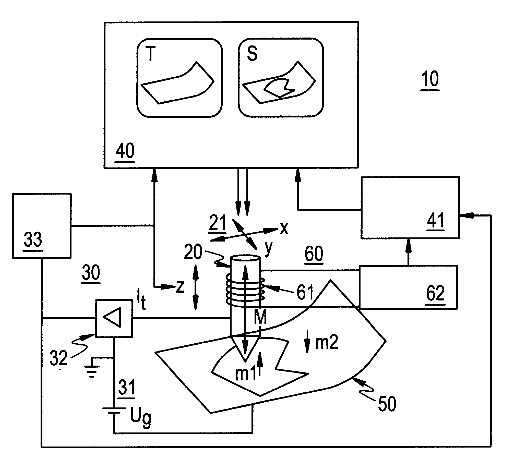
According to FIG. 1, a scanning microscope 10 according to the invention comprises a tunnel tip 20, which is adapted for raster scanning of the surface of the sample 50 in an evacuated sample chamber (not shown) at a distance from this, a control circuit 30, a display and evaluation system 40 and a magnetization device 60. The invention is not limited to applications with a scanning microscope operated in an evacuated sample chamber, but is able to be implemented for scanning microscopy in an electrolyte or in an inert gas. The tunnel tip 20 may be moved in the x, y and z directions using a piezoelectrical drive 21. The details of the piezoelectrical drive 21, the control circuit 30 with the bias voltage circuit 31, the current / voltage converter 32 and the z controller 33 and the display and evaluation system 40, to the extent as the display of topographic surface characteristics are concerned, are known from conventional scanning microscopes and are, therefore, not described in det...


PUM


Abstract

In a method for scanning microscopy, for which the surface of a sample is scanned point-by-point using a tunnel tip and locally resolved tunnel current measurement is performed, during scanning the tunnel tip is remagnetized by a predetermined remagnetization frequency, and from the tunnel current (It) or a z coordinate of the distance between the tunnel tip and the sample or a value derived from this, locally resolved signal components are derived, occurring at the remagnetization frequency and being characteristic for magnetic sample properties, whereby on the basis of the derived signal components an imaging of the magnetic structure of the sample surface is performed.

Description

The invention concerns a method for tunnel microscopy, especially a tunnel microscopy method for recording the magnetic, spin or susceptibility structure of a sample, and a tunnel micro scope (a so-called "spin-polarized tunnel microscope") for implementation of the method as well as methods for use of such a tunnel microscope.PRIOR ARTA traditional tunnel microscope, for instance as described by G. Binnig et al. in "Phys. Rev. Lett.", Vol. 49, 1992, p. 57 ff., is shown in the diagram in FIG. 6. The tunnel microscope 10' is designed for non-contact scanning of a sample 50' on the basis of the tunnel effect. The tunnel microscope 10' specifically includes a tunnel tip 20' with a piezo-electrical drive 21', a control circuit 30' and a display and evaluation system 40'. The tunnel tip 20' typically consisting of tungsten is moved across the surface of the sample 50' using the piezo-electrical drive 21' for scanning in the x and y directions. During scanning, the tunnel current between ...

Claims


Application Information

Patent Timeline
IPC IPC(8): G01R33/038G11B5/00G11B9/00G01Q60/02G01Q60/14G01Q60/50
CPCB82Y35/00G01Q60/02G01Q60/14G01Q60/50G01R33/0385G11B5/00G11B9/1409B82Y10/00B82Y25/00G11B2005/0002G11B2005/0005Y10S977/881Y10S977/861Y10S977/865
Inventor KIRSCHNER, JURGENWULFHEKEL, WULF
Owner MAX PLANCK GESELLSCHAFT ZUR FOERDERUNG DER WISSENSCHAFTEN EV
Why Eureka
Try Eureka