Resonant power converter

Inactive Publication Date: 2002-11-19
TDK LAMBDA CORP
View PDF22 Cites 49 Cited by
  • Summary
  • Abstract
  • Description
  • Claims
  • Application Information

AI Technical Summary

Problems solved by technology

However, in the prior art resonant power converter, since the resonance caused between the resonance capacitor C21 and resonance coil L24 and the primary coil L21 of the transformer Tr21 is utilized, there is a problem in that the energizing current for the transformer Tr21 becomes too large, which results in large energy loss and an increased size of the transformer Tr21.
Further, there is another problem in that this arrangement requires to have the center tap in the secondary coil L2 of the transformer Tr21, which results in complicated structure of the transformer Tr21.
In addition, in the prior art resonant power converter, since the diodes D21, D22 are used as the rectifying means, a large voltage drop occurs in these elements.
Therefore, when such a power converter is c

Method used


Image

  • Resonant power converter
  • Resonant power converter
  • Resonant power converter

Examples


Example

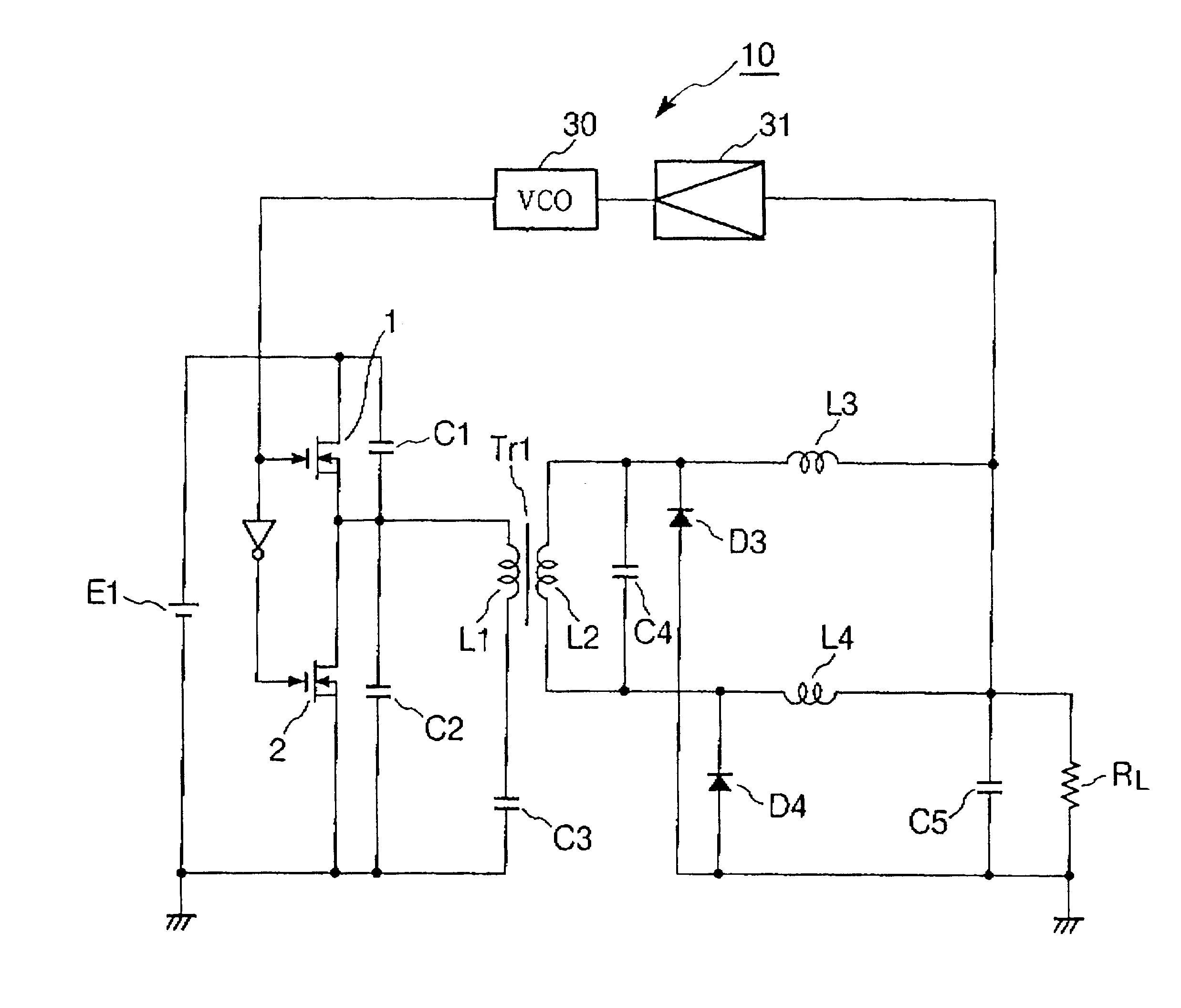
First, FIG. 1 is a circuit diagram showing the circuit configuration of a first embodiment of a resonant power converter according to the present invention. As shown in this circuit diagram, a resonant power converter 10 is equipped with a DC power source E1, two MOS-FETs 1, 2 (switching means) connected in series with respect to the DC power source E1, a voltage controlled oscillator (hereinafter, referred to-as a VCO) 30 for controlling the frequency of the driving signals supplied to the MOS-FETs 1, 2, a capacitor C1 connected in parallel with the MOS-FET 1, a capacitor C2 connected in parallel with the MOS-FET 2, and a transformer (resonant transformer) Tr1 which includes a primary coil (winding) L1 and a secondary coil (winding) L2. In this arrangement, one end of the primary coil L1 of the transformer Tr1 is connected to the junction between the MOS-FETs 1, 2, and the other end is connected to the negative side of the DC power source E1 via a capacitor C3.

The VCO 30 turns the ...

Example

Hereinbelow, a description will be made with regard to the second embodiment of the present invention based on FIG. 8 to FIG. 15. In this connection, it is to be noted that the same or corresponding components or parts as those of the first embodiment are designated with the same reference numerals.

FIG. 8 is a circuit diagram which shows the second embodiment of the resonant power converter of the present invention. As is the same with the first embodiment shown in FIG. 1, the resonant power converter 100 is equipped with a DC power source E1, two MOS-FETs 1, 2 (switching means) connected in series with respect to the DC power source E1, a voltage controlled oscillator (hereinafter, referred to as a VCO) 30 for controlling the frequency of the driving signals supplied to the MOS-FETs 1, 2, a capacitor C1 connected in parallel with the MOS-FET 1, a capacitor C2 connected in parallel with the MOS-FET 2, and a transformer (resonance transformer) Tr1 which includes a primary coil (windi...


PUM


Abstract

A resonant power converter includes a DC power source 1, a pair of MOS-PETs 1 and 2 which are connected in series to the DC power source, a transformer Tr1 which is arranged at the subsequent stage of the MOS-FETs 1 and 2 and includes a primary coil and a secondary coil, a capacitor C4 is arranged in parallel with the secondary coil of the transformer Tr1 so that series resonance occurs between the leakage inductance of the transformer Tr1 and the capacitor C4. A current doubler rectifier circuit may be arranged in the subsequent stage of the capacitor C4. Further, a pair of switching elements for synchronous rectification may be provided in the subsequent stage of the capacitor C4 so that these switching elements are driven by drive signals responsive to a voltage generated across the resonance capacitor C4.

Description

1. Field of the InventionThis invention relates to a DC power converter (DC power supply), and more particularly to a resonant power converter which is capable of performing zero voltage switching (ZVS) with reduced noise.2. Description of the Prior ArtIn general, a 5 to 10 volt DC power converter is required to operate the semiconductor integrated circuits used in electrical and electronic equipment such as personal computers and AV equipment. In the prior art, as for such DC power converters, power converters using a switching regulator are employed. Such DC power converter using the switching regulator can be formed into a compact size rather than other types of DC power converters using series regulators and shunt regulators and the like. Further, such DC power converters have advantages in that power loss is small and energy conversion efficiency is high. Recently, in order to achieve even greater reductions in power loss, resonant switching converters which are capable of zero...

Claims


Application Information

Patent Timeline
IPC IPC(8): H02M3/335H02M3/24
CPCH02M3/33569H02M3/33592Y02B70/1433Y02B70/1475Y02B70/10H02M3/33571H02M3/01
Inventor TERASHI, HIROTO
Owner TDK LAMBDA CORP
Why Eureka
Try Eureka