
Method of manufacturing a ferritic-martensitic, oxide dispersion strengthened alloy

a technology of oxide dispersion and manufacturing method, which is applied in the direction of fuel elements, climate sustainability, reactor fuel elements, etc., can solve the problems of high anisotropy in its mechanical properties, too low mechanical strength, and brittleness

Inactive Publication Date: 2002-11-26
COMMISSARIAT A LENERGIE ATOMIQUE ET AUX ENERGIES ALTERNATIVES
View PDF11 Cites 23 Cited by
  • Summary
  • Abstract
  • Description
  • Claims
  • Application Information

AI Technical Summary

Benefits of technology

In an advantageous way, the blank can be prepared from a pre-alloyed powder obtained by mechanical alloying. In effect the mechanical alloying makes possible the dispersion of oxides such as Y.sub.2 O.sub.3 required for the preparation of an ODS alloy.

Problems solved by technology

However the grains that make it up are elongated in the direction of forming which leads to a high degree of anisotropy in its mechanical properties.
This anisotropy leads to too low a mechanical strength along directions perpendicular to the direction of forming.
In addition, this alloy contains a high level of chromium which causes it to become brittle under neutron radiation through the precipitation of phases rich in this element.
Under these conditions, too small a grain size causes a reduction in the mechanical strength of the alloy, particularly at high temperatures greater than 500.degree. C.
Furthermore, the anisotropy of the grain size leads to anisotropy in the mechanical properties of the alloy.
In order to avoid these problems of anisotropy, a man skilled in the art has been drawn into using a martensitic material less rich in Cr, but in this case, control of the mean grain size has proved to be impossible.
However the method described does not allow one to control the grain size of the alloy.
they do not allow one to obtain an isotropic microstructure of the formed alloy,
they do not allow one to specify and control the grain size of the alloy
they lead to a grain size that remains too small.
insufficient mechanical strength at high temperature due to the anisotropy of its microstructure,
a mechanical strength that is not always compatible with use at high temperature and / or under neutron irradiation due particularly to having no control over the grain size of the alloy and to the grain size being too small.

Method used


Image

  • Method of manufacturing a ferritic-martensitic, oxide dispersion strengthened alloy
  • Method of manufacturing a ferritic-martensitic, oxide dispersion strengthened alloy
  • Method of manufacturing a ferritic-martensitic, oxide dispersion strengthened alloy

Examples


example 1

Preparation of Ferritic-martensitic Allows and Examples of Fe-9 Cr-1 Mo alloys

The alloys manufactured in this example, according to the method of the invention, are alloys of the 9 Cr-1 Mo type, based on iron, named EM10 in what follows, and strengthened by particles of yttrium oxide.

Each of these alloys is manufactured by a mechanical alloying method. An ingot having the composition of the alloy desired is atomized under argon in such a way as to obtain a 9 Cr-1 Mo pre-alloyed powder. This pre-alloyed powder is ground and mixed with yttrium oxide (Y.sub.2 O.sub.3) in powder form, in an attritor under an atmosphere of argon. Then the resulting powder is compacted by hot drawing at a temperature of 1100.degree. C. at a drawing ratio of between 15 and 30 in order to obtain a martensitic blank that includes chromium strengthened by the dispersion of oxide particles.

Several alloys are manufactured. The chemical composition of these alloys is shown in Table 1 below. When the alloy contai...

example 2

Effect of the Cooling Rate According to the Invention on the Grain Size of the EM1030 Y.sub.2 O.sub.3 -ODS Alloy with a Ferritic Structure

In this example, the alloy manufactured is an alloy with a ferritic structure.

A series of tests are carried out starting with a martensitic EM10+Y.sub.2 O.sub.3 -ODS blank having the composition described in Table 1, in order to measure the effect of cooling rate on the grain size of the manufactured alloy.

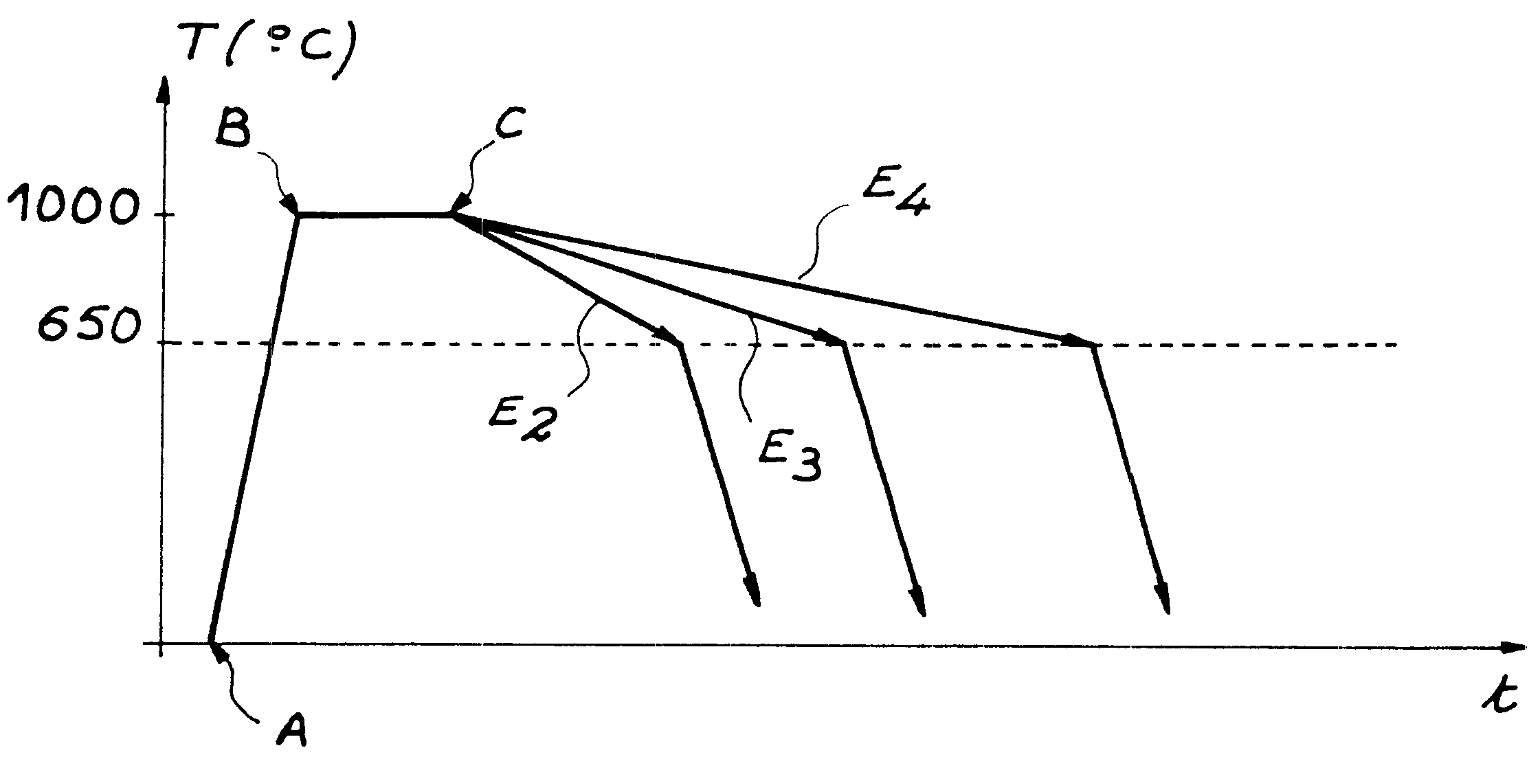
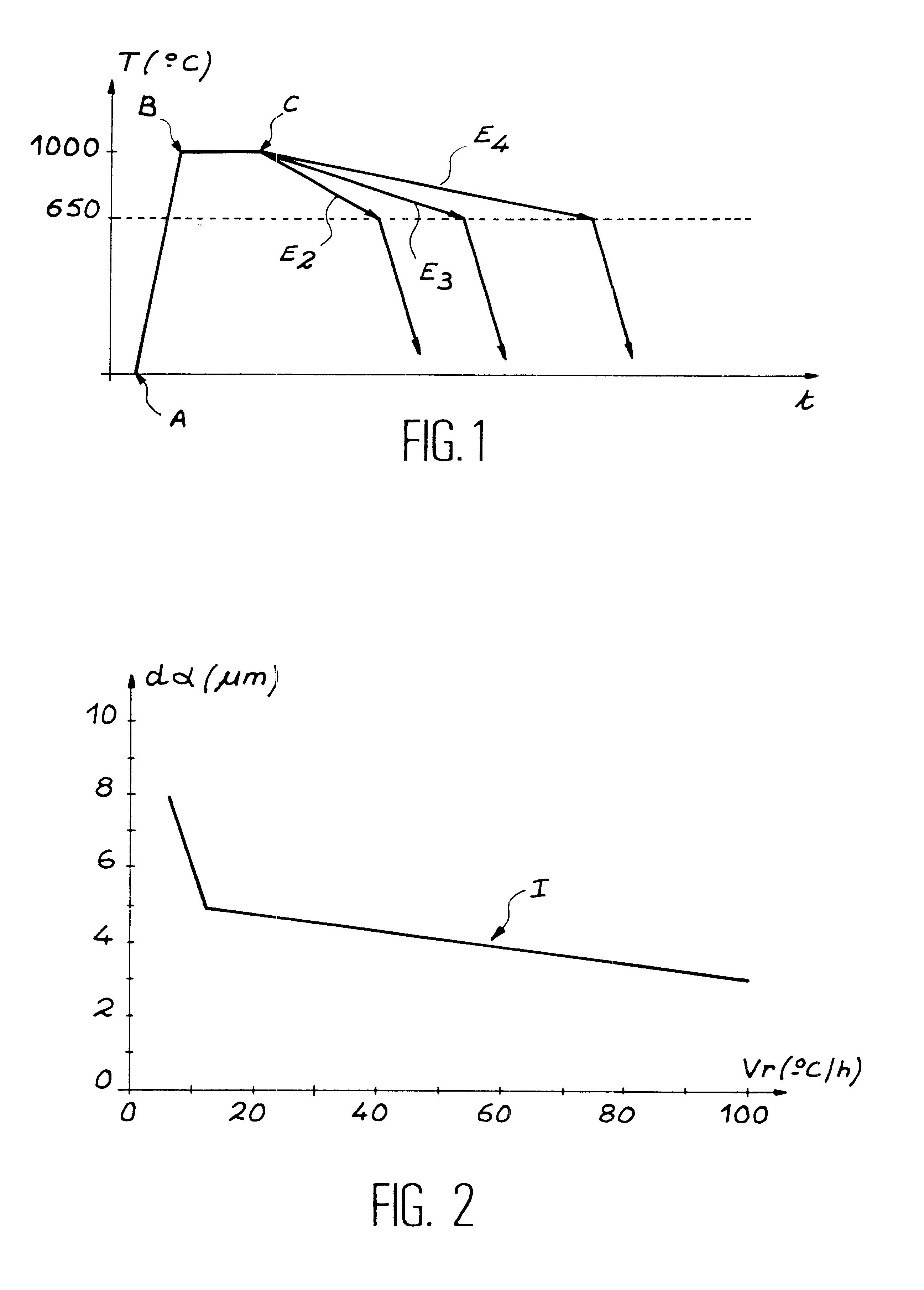
Four samples of the EM10+Y.sub.2 O.sub.3 -ODS alloy were subjected to a first thermal cycle according to the invention, comprising an austenitization at a temperature of 1000.degree. C. for 30 minutes followed by cooling to 650.degree. C., at a rate that was different for each sample, and fast cooling at a common rate of 3.degree. C. per second from 650.degree. C.

Table 2 below shows the cooling rates for each sample (designated E.sub.1, E.sub.2, E.sub.3 and E.sub.4) as far as 650.degree. C.

FIG. 1 is a graph illustrating the thermal cycles of E.s...

example 3

Repetition of a Thermal Cycle According to the Invention on an Alloy with a Ferritic ODS Structure

This example uses an ODS-EM10+Y.sub.2 O.sub.3 alloy such as that described in Table 1 above.

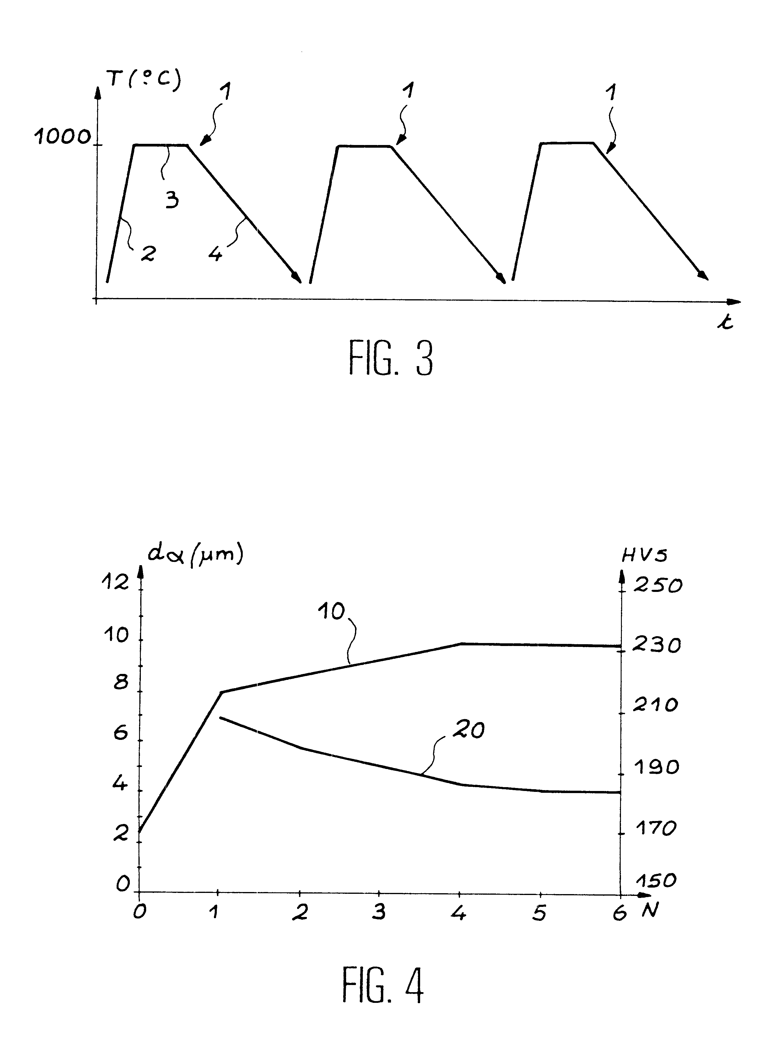
A thermal cycle with slow cooling is applied in a repeated way on this alloy in such a way as to measure the effect of this repetition on the grain size of the alloy.

FIG. 3 illustrates diagrammatically this Example 3, reference number 1 indicating a slow thermal cycle. This thermal cycle comprises an austenitization which consists of heating the alloy to a temperature of 1000.degree. C., indicated by reference number 2, and of holding the alloy at this temperature for 30 minutes, indicated by reference number 3; and then of cooling this alloy at a slow rate of 6.degree. C. / h, indicated by reference number 4. In this Figure, this cycle is repeated 3 times.

Measurements of the mean grain size made using an image analysis technique show that repetition of the thermal cycle according to the invention ...


PUM

PropertyMeasurementUnit
Percent by massaaaaaaaaaa
Angleaaaaaaaaaa
Angleaaaaaaaaaa

Abstract

This invention relates to a method of manufacturing an improved ferritic or martensitic alloy based on iron and chromium strengthened by a dispersion of oxides, commonly called an Oxide Dispersion Strengthened or ODS alloy, and, more particularly to a method of manufacturing a ferritic or martensitic ODS alloy with large grains based on iron and chromium which has a single phase ferritic or martensitic matrix having an isotropic microstructure and a grain size that is sufficient to guarantee mechanical strength compatible with a use of this alloy at high temperature and / or under neutron irradiation. According to the invention, the method comprises slow cooling of an austenite at a cooling rate less than or equal to the critical cooling rate for transformation of this austenite into ferrite.

Description

TECHNOLOGICAL FIELD OF THE INVENTIONThis invention relates to a method of manufacturing an improved ferritic or martensitic alloy, including chromium and which is strengthened by a dispersion of oxides, commonly called an ODS (Oxide Dispersion Strengthened) alloy, and more particularly, to a method of manufacturing a ferritic or martensitic ODS alloy with large grains based on iron and chromium which has single phase ferritic or martensitic matrix having an isotropic microstructure and a grain size that is sufficient to guarantee mechanical strength compatible with a use of this alloy at high temperature and / or under neutron irradiation.ODS alloys are made up of a metal matrix having a body-centered cubic crystal structure. This structure is strengthened by a dispersion of oxides of the type Y.sub.2 O.sub.3, TiO.sub.2 etc. which gives it excellent mechanical and chemical properties at medium and high temperatures.The resistance to oxidation of these alloys is due particularly to the...

Claims


Application Information

Patent Timeline
IPC IPC(8): C22C32/00C22C38/44C22C38/22C22C1/10C21D6/00G21C3/02G21C3/07C21D1/78G21C5/00C22C1/05C22C33/02C22C38/00
CPCC21D6/002C22C1/1094C22C32/0026C22C38/22C22C38/44G21C3/07C21D2211/005Y02E30/40C22C1/1084Y02E30/30
Inventor LAMBARD, VERONIQUEALAMO, ANASERAN, JEAN-LOUIS
Owner COMMISSARIAT A LENERGIE ATOMIQUE ET AUX ENERGIES ALTERNATIVES
Learn More