High resolution, high pressure xenon gamma ray spectroscopy using primary and stimulated light emission

a gamma ray spectroscopy and high-pressure technology, applied in the direction of x/gamma/cosmic radiation measurement, separation processes, instruments, etc., can solve the problems of inability to achieve high-voltage levels, affecting the energy resolution of such a large hpxe ionization chamber, and affecting the construction of large hpxe parallel-plate ionization chambers

Inactive Publication Date: 2002-11-26
PROPORTIONAL TECH
View PDF1 Cites 42 Cited by
  • Summary
  • Abstract
  • Description
  • Claims
  • Application Information

AI Technical Summary

Problems solved by technology

Incomplete shielding from the shielding grid, and the high capacitance of the parallel-plate geometry, and the nearby grid, significantly decreases the energy resolution of such an HPXe ionization chamber.
Furthermore, construction of a large HPXe parallel-plate ionization chamber is severely hampered by the bulk of the pressure vessel necessary to contain a large volume of the gas, which dictates a flat, not round, exterior surface.
Additionally, the high electric field required to prevent electron-ion recombination in HPXe (2000-4000 V / cm) requires high voltage levels which are impractical for an electron drift distances over 10 to 15 cm.
Finally, the mechanical instability of the shielding grid structure leads to serious microphonic noise sensitivity.
Without correction, relatively poor energy resolution is obtained.
So far, no method to accurately determine this radial coordinate has been reported.
Cylindrical ionization chambers employing a Fritch grid have only achieved energy resolution figures of approximately 2% FWHM, similar to planar grid devices, and no group has been able to approach the intrinsic energy resolution of HPXe.

Method used


Image

  • High resolution, high pressure xenon gamma ray spectroscopy using primary and stimulated light emission
  • High resolution, high pressure xenon gamma ray spectroscopy using primary and stimulated light emission
  • High resolution, high pressure xenon gamma ray spectroscopy using primary and stimulated light emission

Examples


Embodiment Construction

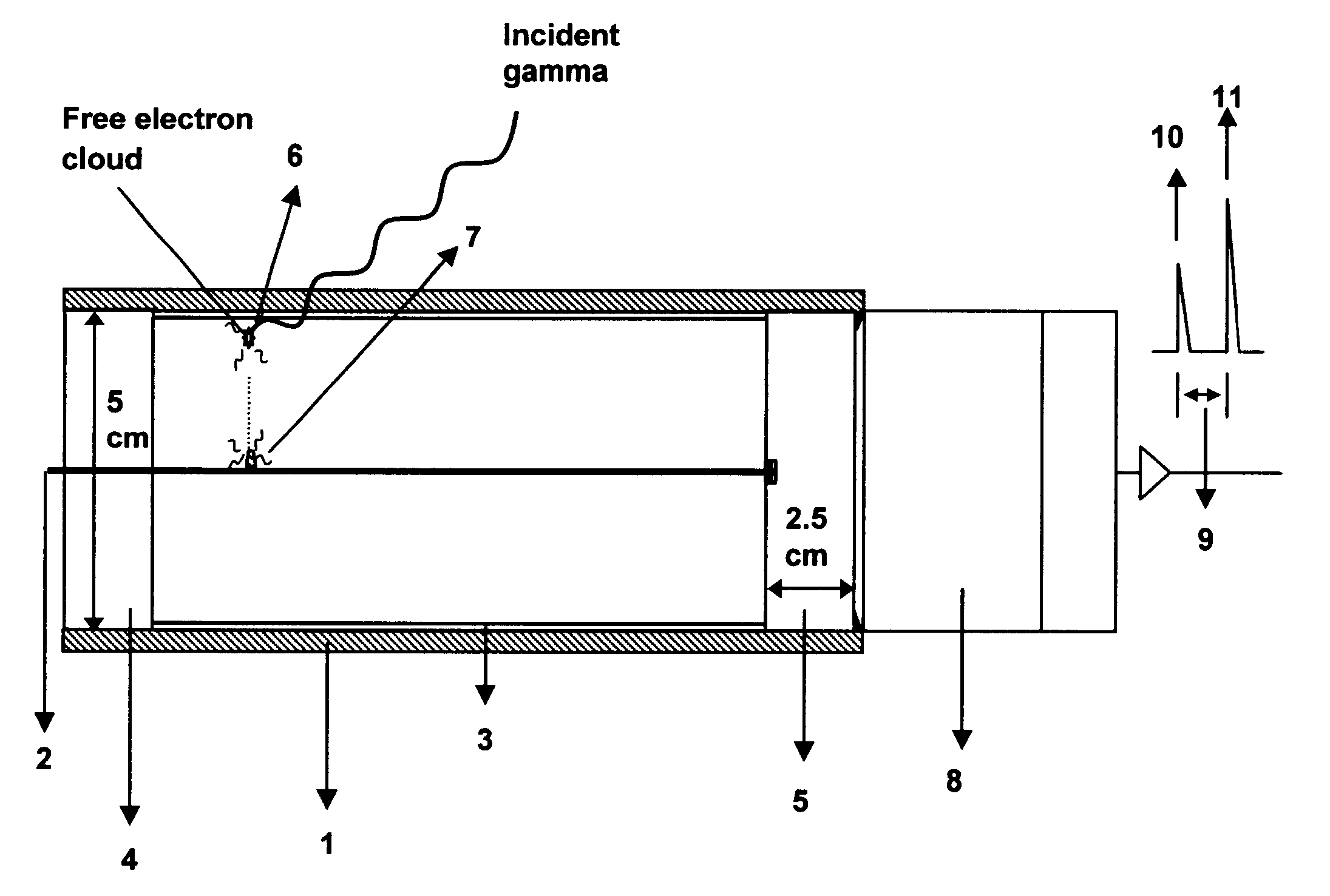
The use of scintillation light, in a manner as described, has been achieved by constructing a detector with a VUV transmitting end window constructed of MgF.sub.2. An anode wire of 20 gm diameter was affixed in the center of this MgF.sub.2 window crystal by epoxying it into a shallow hole drilled in the inner surface of the window. The wire was then tensioned in the aluminum tube of 4 mm inside diameter and 5 cm length. The tube, serving as the cylindrical conducting cathode electrode, was then filled to a pressure of 48 atmospheres with high-purity xenon and coupled to a quartz window PMT (Electron Tubes #9235) through an inert argon gas space. Tube excitation was produced by a Tc-99m (0.3 .mu.Ci) point source placed near the detector surface. With such a source placed 1 cm from the light transmitting MgF.sub.2 crystal, the phototube output signal was taken at a series of HPXe anode voltages of 0 volts, 800 volts, and 1500 volts. Operation with no collection field (0 volts) demonst...


PUM


Abstract

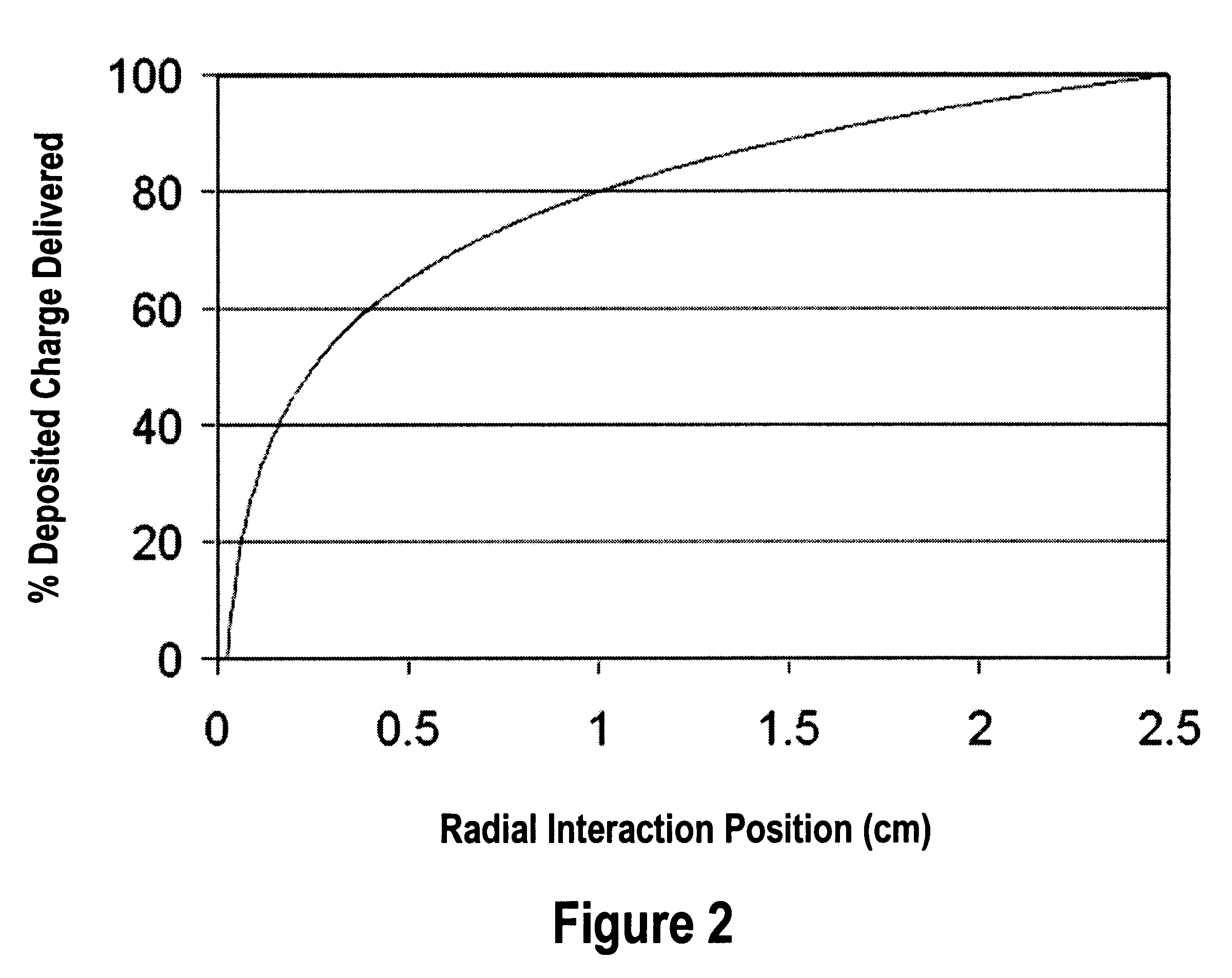
A design and readout of a xenon detection medium based device, which provides improved spectroscopic performance compared to currently commercially available devices. To achieve energy resolution improvement, a method to accurately measure radial spatial position for interacting events within a HPXe cylindrical detector is described using the plan as shown in FIG. 4. This is accomplished by utilization of light generated both at the gamma interaction site and at the collection point near the anode wire of the cylindrical detector. These light flashes are detected by a VUV photon detector. Light transmission is facilitated by incorporating a vacuum ultraviolet (VUV) light transparent window at least one end of the cylindrical ionization detector. With the known electron drift velocity in HPXe, the time between these two photopulses is sufficient to accurately determine the radial coordinate. Consequently, correction by electronic means for the electrostatic pulse dispersion using the expression graphed in FIG. 2 can be achieved in order to approach the true intrinsic energy resolution limit for HPXe.

Description

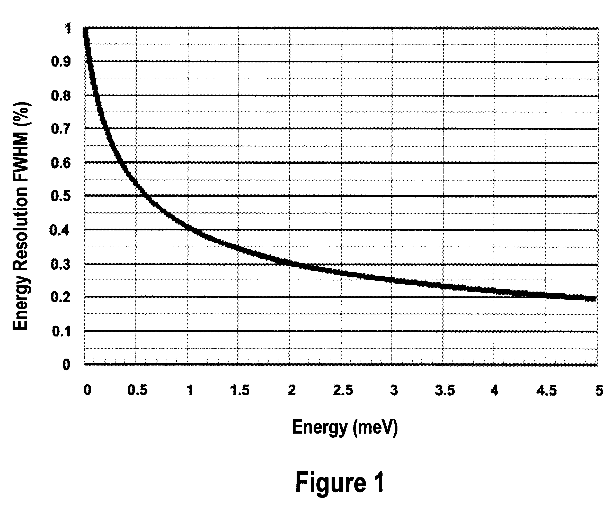
Not applicable.Not applicable.1. Field of the InventionDevices for high-resolution gamma ray spectroscopy.2. Description of the Related ArtEnergy measurements of gamma rays in the energy range 100 keV to 10 MeV are of great use in many fields including; medical imaging, astrophysics, environmental monitoring and general nuclear spectroscopy.High-pressure xenon (HPXe) has a potential to provide a medium with excellent spectroscopic characteristics. Excellent spectroscopic resolution of the xenon gas (0.6% full width half maximum (FWHM) energy resolution) is preserved up to a xenon gas density of 0.55 g / cm.sup.3. Above this density, resolution degrades, eventually reaching the levels found in liquid xenon (LXe) at very high densities. Therefore, HPXe at 0.55 g / cm.sup.3 is ideal because of its excellent energy resolution (0.6% FWHM at 662 keV and 0.4% FWHM at 1 MeV) and high stopping power (density 0.55 g / cm.sup.3 and high Z of 54). The expected energy dependence of xenon resolution at...

Claims


Application Information

Patent Timeline
Patent Type & Authority Patents(United States)
IPC IPC(8): G01T1/00G01T1/185
CPCG01T1/185
Inventor LACY, JEFFREY L.
Owner PROPORTIONAL TECH
Why Eureka
Try Eureka