Tool path measurement

a tool path and measurement technology, applied in the field of tool path measurement, can solve the problems of rather achieve the effect of minimizing angular shifting problems, large and small tolerance for lateral displacemen

Inactive Publication Date: 2002-12-24
OPTODYNE
View PDF4 Cites 31 Cited by
  • Summary
  • Abstract
  • Description
  • Claims
  • Application Information

AI Technical Summary

Benefits of technology

Briefly, conventional laser interferometers using a retroreflector as the target mounted on the machine tool spindle can measure the linear displacement relative to a single axis thereof accurately. However, the tolerance for lateral displacement is rather small. Using preferably a single-aperture (or less desirable modified prior art two-aperture) laser target displacement measuring system like the Laser Doppler Displac

Problems solved by technology

However, the tolerance for later

Method used


Image

  • Tool path measurement
  • Tool path measurement
  • Tool path measurement

Examples


Embodiment Construction

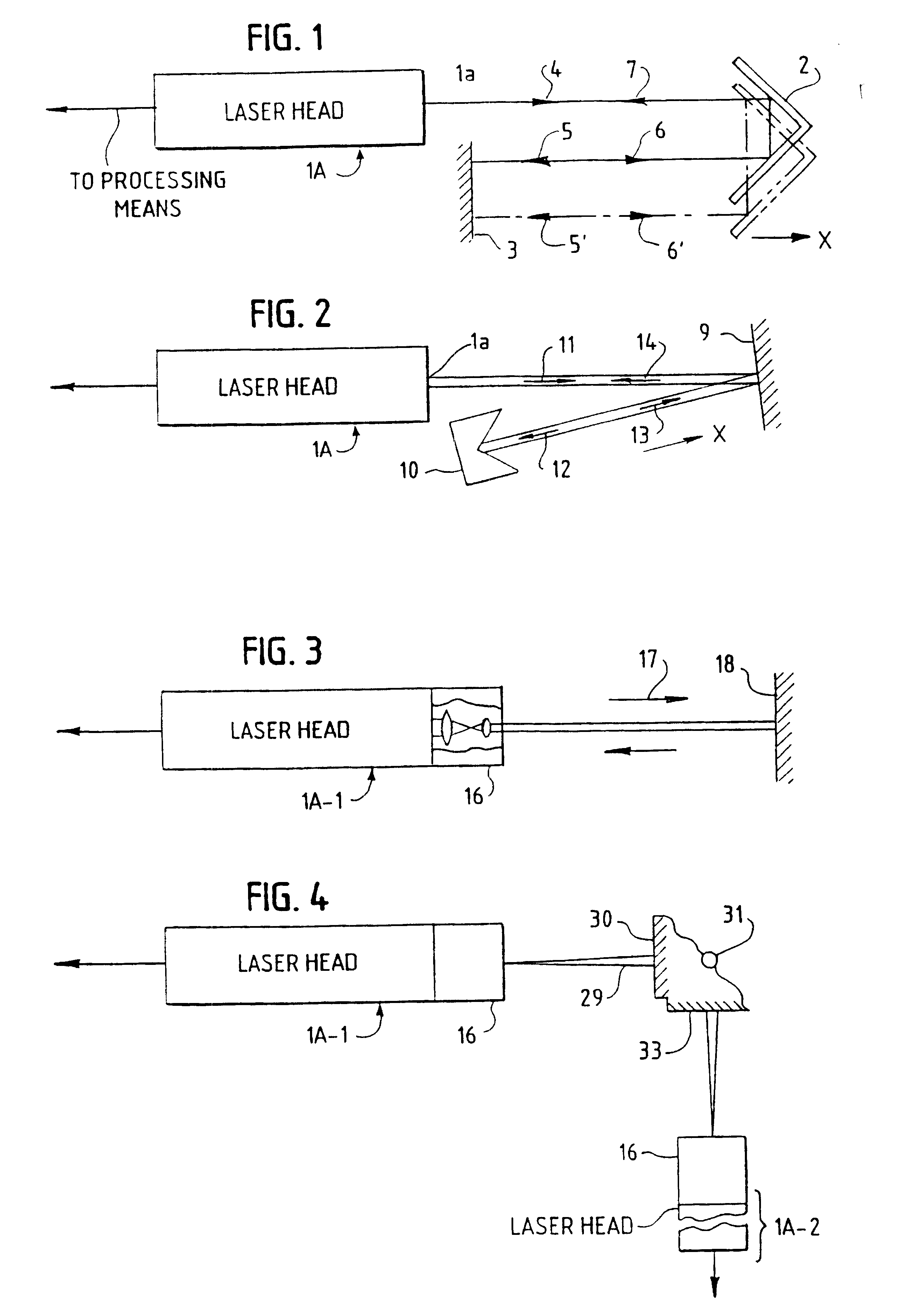
The double-path parallel beam laser system shown in FIG. 1 consists of a single-aperture laser head 1A, an unconventionally large retroreflector 2 and a flat-mirror 3. (For example, the retroreflector could be as large as 10" inches in diameter.) The laser head's output laser beam 4 is first reflected by the large retroreflector 2 to produce a first reflected beam 5 parallel to but displaced from output beam 4. The flat mirror 3 is perpendicular to the first reflected beam 5, hence the flat mirror-reflected beam 6 coincides with the first reflected beam 5, but in the opposite direction. The latter beam 6 is reflected again by the large retroreflector 2 to form return beam 7 which coincides with output beam 4 but in the opposite direction and is returned to the single laser head aperture. It is noted that the property of the retroreflector 2 is that the incident beam direction and the reflected beam direction are parallel and in the opposite direction. This property is not affected b...


PUM


Abstract

The degree of accuracy a machine tool or the like is moved along a given path is determined by a unique preferably laser beam directing measuring system directing simultaneously or in sequence a laser beam parallel to the orthogonal axes of the two or three dimensional space in which the spindle or other object is to be moved in a path which can diverge appreciably in directions other than the directions of these axes. The beam directing means includes means which provides a measure of the actual positions the object has at various sampling times relative to the axis along which the beam is directed. This actual path position data is compared to the desired path position data used to program the object moving machine to determine the path position error at the sampling times involved.

Description

II. BACKGROUND OF INVENTIONFor the machining of precision and quality parts, it is important to measure the machine accuracy and performance both at static conditions (low speed or stopped) and at dynamic conditions (high speed and multiple-axis). Laser interferometers have been used for the measurement of machine positioning accuracy at static conditions and relative to the position accuracy along each of the axes involved. That is, the measurements were not taken as the machine spindle was moving relative to the X, Y and Z axes involved for reasons including the fact that the laser systems which reflected a laser beam off of a retroreflector carried by the spindle could not intercept the reflected beam to make a measurement as the spindle was intentionally moved appreciably relative to these axes. The laser interferometer systems disclosed in said PCT application Ser. No. US 99 / 14815 do not have this severe problem.A prior art device which can make such measurements but under rela...

Claims


Application Information

Patent Timeline
IPC IPC(8): G01B11/30G01B11/00G01B11/03G01B21/04G05B19/25G05B19/401
CPCG01B11/005G01B11/306
Inventor WANG, CHARLES
Owner OPTODYNE
Why Eureka
Try Eureka