Layer structure including metallic cover layer and fiber-reinforced composite substrate, and a method of making the same

a fiber-reinforced composite and metallic cover technology, applied in the direction of film/foil adhesives, synthetic resin layered products, transportation and packaging, etc., can solve the problems of insufficient adhesion ability, inability to provide adequate adhesion, and inability to meet the requirements of the substrate,

Inactive Publication Date: 2003-02-18
MTU AERO ENGINES GMBH
View PDF7 Cites 42 Cited by
  • Summary
  • Abstract
  • Description
  • Claims
  • Application Information

AI Technical Summary

Problems solved by technology

Such layer structures based on fiber composite materials, however, have a relatively low resistance to erosive wear.
In this context, it has been discovered that the reliability and durability of the adhesive bonding of the metal sheet onto the underlying fiber composite structure is problematic and inadequate in practice.
Such a layered body, however, does not provide an adequate adhesion ability for various functional layers that are to be applied thereon without chemically or physically attacking the resin matrix.
As a result, the metallic fibers and / or threads are not easily separated due to external loads being applied to the layer structure, or even due to cracking of the resin matrix itself.
If a fiber rupture should occur nonetheless, the rupture damage will remain locally limited, since each fiber of a fleece does not extend continuously throughout the entire fleece layer, but rather has a limited length, in contrast to a woven web of threads, in which each thread generally extends continuously through the entire width or length of the woven web.

Method used


Image

  • Layer structure including metallic cover layer and fiber-reinforced composite substrate, and a method of making the same
  • Layer structure including metallic cover layer and fiber-reinforced composite substrate, and a method of making the same
  • Layer structure including metallic cover layer and fiber-reinforced composite substrate, and a method of making the same

Examples


Embodiment Construction

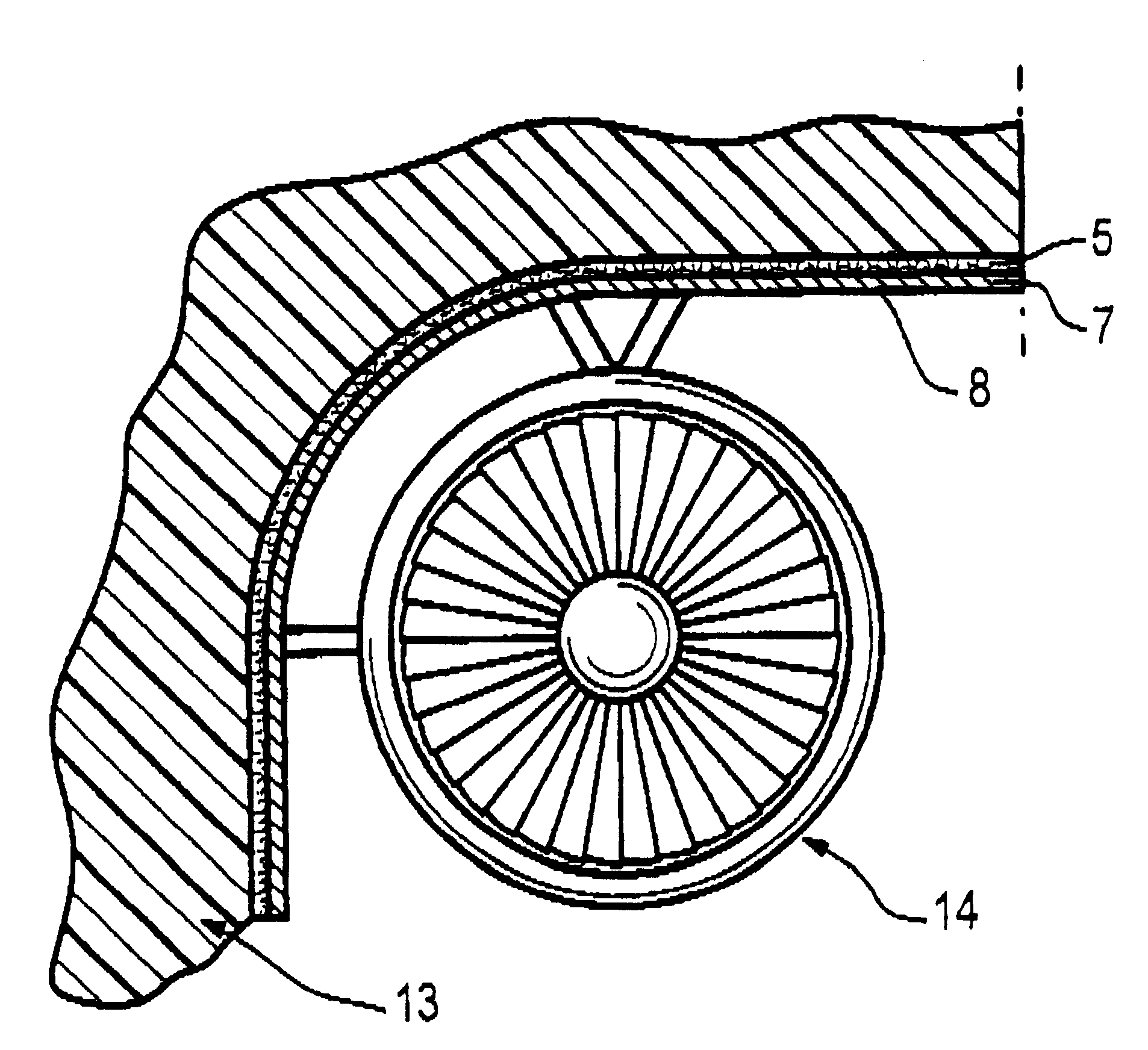
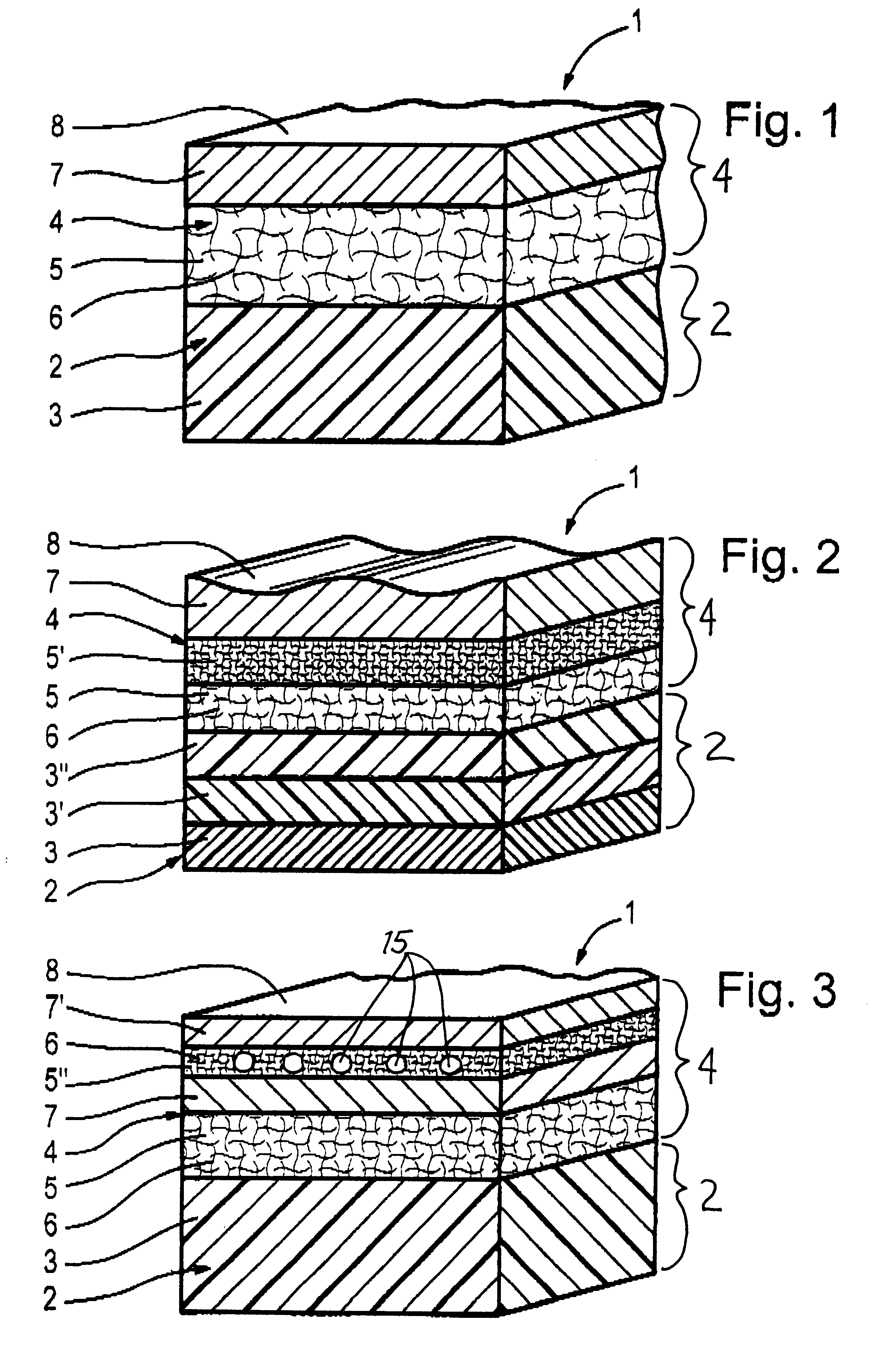
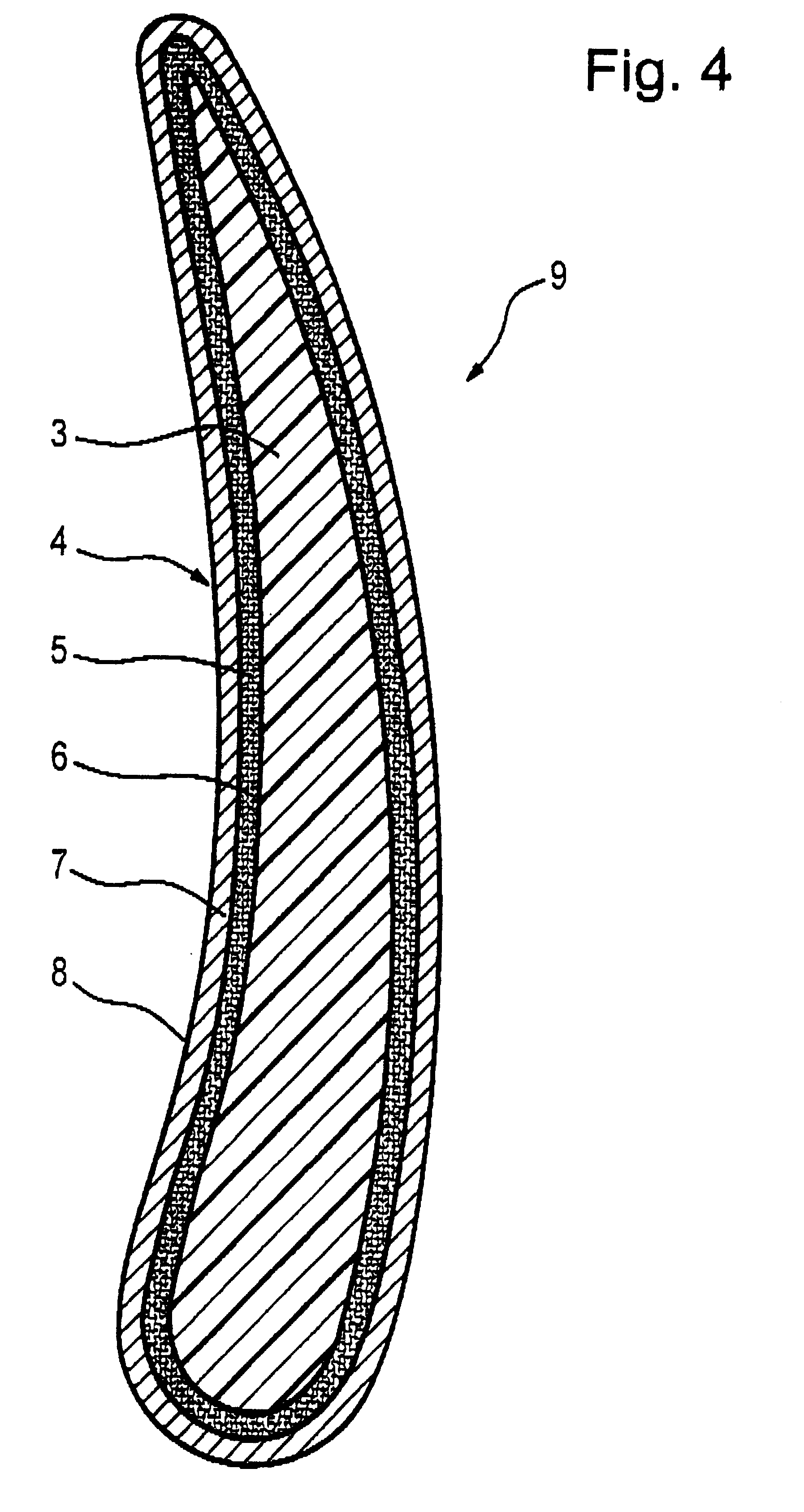
FIG. 1 shows an example embodiment of a layer structure 1 that includes a cover layer 4 arranged on a substrate 2. The substrate 2 essentially consists of a layer of fiber-reinforced synthetic material 3. The cover layer 4 comprises an interface layer 5 of metallic fibers and / or threads 6 adjacent to and bonded to the underlying substrate layer of fiber-reinforced synthetic material 3. The cover layer 4 further comprises a metal sheet 7 forming the outer surface or outer skin 8 of the layer structure 1. The metallic fibers and / or threads 6 and the metal sheet 7 consist of the same metallic material.

A first step in manufacturing the layer structure 1 involves sintering the threads and / or fibers 6 to the metal sheet 7 at a temperature of about 10.degree. C. below the melting temperature of their metallic material, so as to bond the materials together to form the cover layer 4. The manufacturing method next involves bonding the cover layer 4 with the substrate 2, as discussed below.

The...


PUM

PropertyMeasurementUnit
melting temperatureaaaaaaaaaa
lengthaaaaaaaaaa
aspect ratioaaaaaaaaaa

Abstract

A composite laminate or layer structure includes a substrate (2) and a cover layer (4) bonded thereon. The substrate is made up of at least one layer (3) of fiber-reinforced synthetic material. The cover layer includes at least one layer (5) of metal fibers and/or threads (6), and a metal sheet (7) forming the outer surface skin (8) of the layer structure. The metal sheet is bonded by soldering or sintering onto the metal fibers and/or threads (6), while the layer of metal fibers and/or threads in turn is bonded to the underlying fiber-reinforced synthetic material (3) by being mutually and integrally permeated by a synthetic resin matrix and bonding material. Also, the metal fibers and/or threads (6) may be intermeshed with the fibers of the synthetic material (3). To provide improved bonding at both opposite sides thereof, the layer (5) of metal fibers and/or threads (6) has a lower porosity on the side adjoining the metal sheet, and a higher porosity on the side adjoining the fiber-reinforced synthetic material (3) of the substrate.

Description

PRIORITY CLAIMThis application is based on and claims the priority under 35 U.S.C. .sctn.119 of German Patent Application 199 09 675.9, filed on Mar. 5, 1999, the entire disclosure of which is incorporated herein by reference.The invention relates to a composite layer structure for use on structural components subject to a danger of erosion damage, including at least one fiber-reinforced synthetic material layer as a substrate, and a cover layer that includes at least one layer of metallic fibers and / or threads arranged adjacent to the substrate. The invention further relates to a method of manufacturing such a layer structure.BACKGROUND INFORMATIONLayer structures or laminates embodied in the manner of fiber-reinforced composites combine the advantages of a low weight as well as a sufficient strength. Such layer structures based on fiber composite materials, however, have a relatively low resistance to erosive wear. For this reason, such fiber composite layer structures must be pro...

Claims


Application Information

Patent Timeline
Patent Type & Authority Patents(United States)
IPC IPC(8): B29C70/00B32B27/04B29C70/88
CPCB29C70/885B32B27/04Y10T428/266Y02T50/433Y10T428/249923Y10T428/249924Y02T50/40B32B15/18B32B15/14B32B2605/18B32B2262/103B32B5/26B32B2260/046B32B2260/021B32B2311/22B32B2311/30
Inventor SIKORSKI, SIEGFRIEDSCHOENACHER, REINHOLDSCHOBER, MICHAEL
Owner MTU AERO ENGINES GMBH
Why Eureka
Try Eureka