to provide a magnetic resonance imaging method wherein the
acquisition time of the magnetic resonance signals is significantly shorter than the
acquisition time required when the known SENSE technique is used.
The invention offers a high degree of freedom in choosing the acquisition trajectory to be followed through the k-space for the acquisition of the magnetic resonance signals. Such an acquisition trajectory according to the invention may give rise to irregular sampling of the k-space. It is notably not necessary to perform the sampling on a regular square grid in the k-space during the acquisition of the magnetic resonance signals. Thus, for example, respective parts of the k-space can be traversed at different speeds. The invention notably offers the possibility of choosing an essentially spiral-shaped trajectory through the k-space. Magnetic resonance signals are then acquired first from a central part of the k-space, so with wave vectors of comparatively
small magnitude, after which magnetic resonance signals are acquired with a continuously faster increasing magnitude of the
wave vector. Such an acquisition along a spiral-shaped trajectory, or a trajectory comprising one or more spiral-shaped steps in the k-space, is particularly suitable for use in
MR angiography. Therein, magnetic resonance images of a patient to be examined are formed immediately after the administration of a
contrast medium to the patient, for example an intravenously injected medium. The magnetic resonance signals from the center of the k-space relate mainly to rather coarse structures in the magnetic resonance image, including the arterial part of the vascular
system of the patient to be examined. The venous part of the vascular system involves mainly much finer structures. When a spiral-shaped trajectory is followed, the magnetic resonance signals can be acquired from the arterial part before the
contrast medium reaches the veins. Because, moreover, sub-sampling is applied, the acquisition of the magnetic resonance signals will not require much time. The combination of sub-sampled acquisition of the magnetic resonance signals and scanning the k-space along a spiral-shaped trajectory enables fast acquisition of magnetic resonance images of the arterial part of the vascular system with a
high spatial resolution.
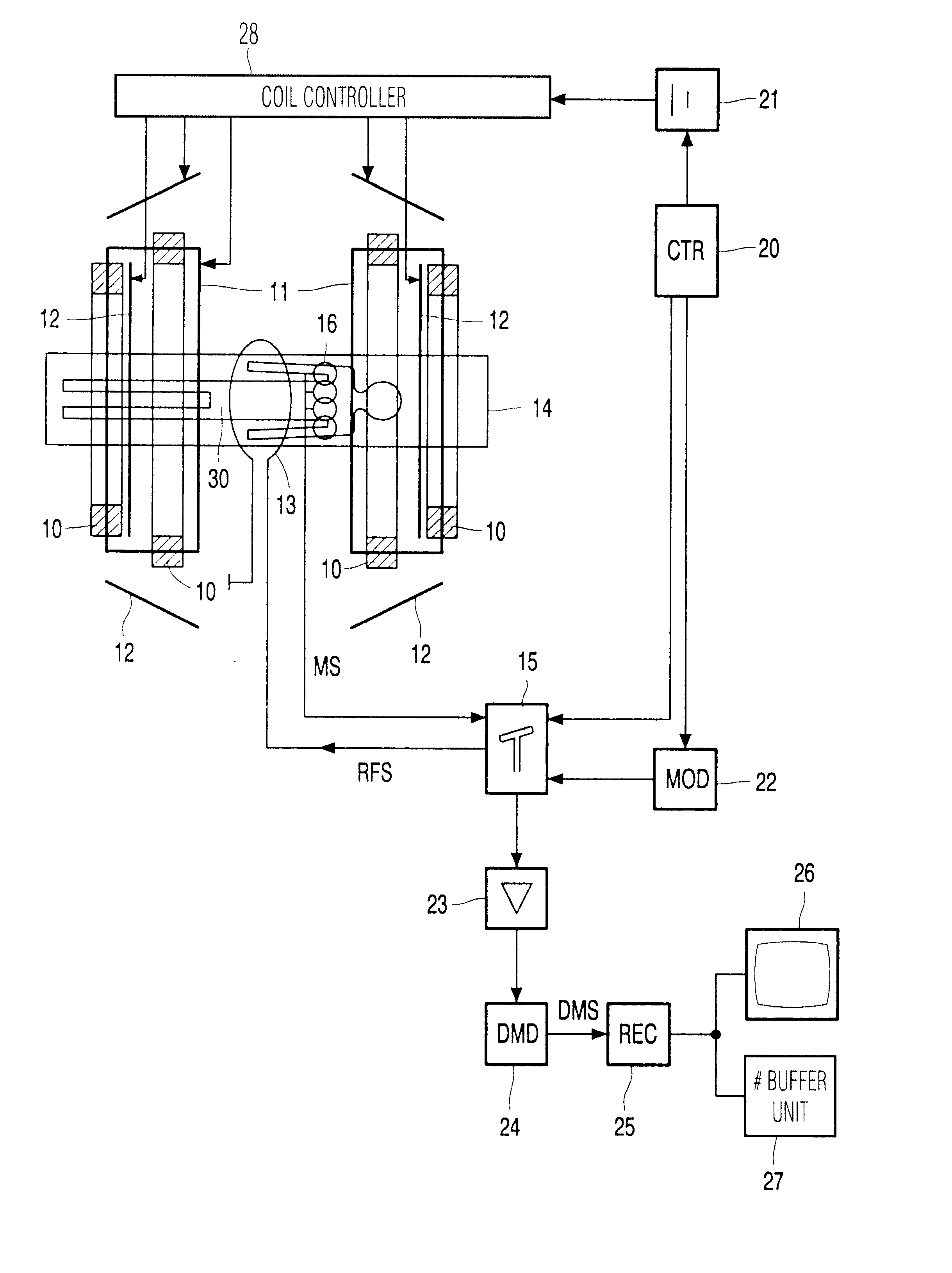
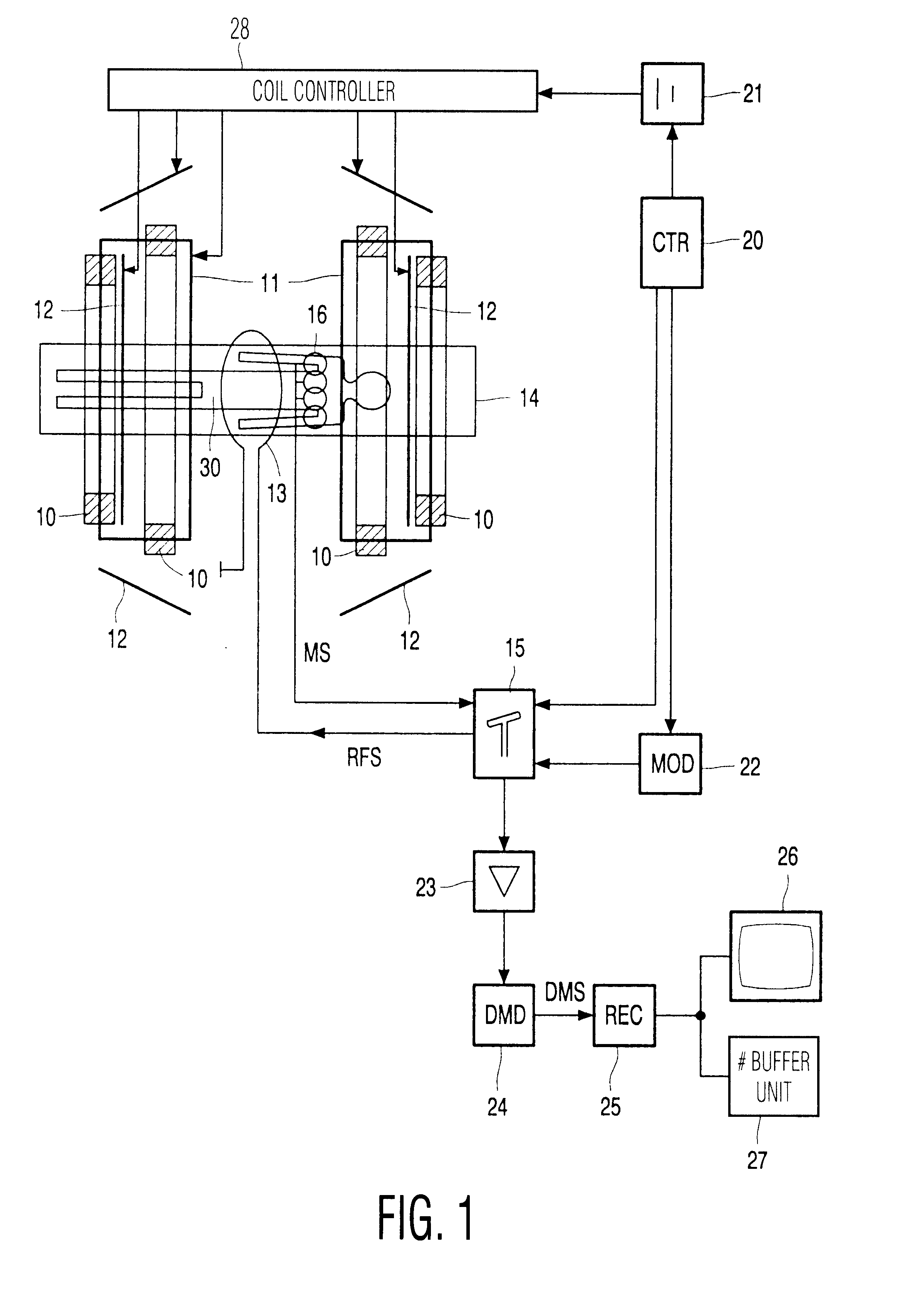
Preferably, respective receiving coil images are reconstructed from the magnetic resonance signals from individual signal channels and from individual receiving antennas. Receiving coils are preferably used as the receiving antennas. Due to the sub-sampling of the magnetic resonance signals from the individual signal channels,
aliasing artefacts such as fold-back phenomena occur in such receiving coil images. The reconstruction of the receiving coil images utilizes the approximated
noise correlation matrix according to the invention. The magnetic resonance image is derived from the receiving coil images on the basis of the sensitivity profiles. The reconstruction of the magnetic resonance image on the basis of the receiving coil image and the sensitivity profiles is known per se as the SENSE method. This SENSE method is known per se from the article by Prussmann et al. in Proceedings ISMRM (1998), 579, and from the article by Prussmann and Weiger in MRM42 (1999), pp. 952-962. The SENSE method enables sub-sampled acquisition of the magnetic resonance signals, thus reducing the time required for the acquisition of the magnetic resonance signals.
Preferably, the receiving coils are preferably decoupled essentially inductively. As the degree of
inductive coupling of the receiving coils is lower, the
noise level and
noise correlation are lower. The
noise level of the magnetic resonance image is thus reduced.
Preferably, an iterative inversion
algorithm is used for the reconstruction of the magnetic resonance image. That is, the magnetic resonance image is reconstructed by iteration from the sub-sampled magnetic resonance signals. Starting with some initial vector, iterative algorithms yield a progression of approximate solutions, which converges to the exact solution. A variety of such techniques exist for the treatment of large linear systems. The so-called conjugate-gradient (cg) method is particularly suited. On the one hand, it may be combined with FFT for very efficient calculations. On the other hand, the CG iteration does not require particular provisions for ensuring convergence. It converges safely given that the matrix involved is positive definite, which holds true for the matrix that connects the pixel-values of the reconstructed magnetic resonance image to the sub-sampled magnetic resonance signals through the gradient encodings and the coils sensitivity profiles. The CG
algorithm theoretically yields the exact solution of an N.sup.2.times.N.sup.2 system after at most N2 iterations. For N in the range of 128, though, it is not practical to carry out the entire procedure until mathematically strict convergence is achieved. However, in practice it appears that approximations leading to a good
diagnostic quality for the reconstructed magnetic resonance image are obtained after a relatively small number of iterations already. Each CG iteration step consists in multiplying the matrix to be inverted with a residuum vector and several further calculations of minor complexity. Thus the iteration speed depends crucially on how fast matrix-vector multiplication can be performed. The number of iterations necessary to achieve a given accuracy is related to the so-called condition of the matrix to be inverted and the suitability of the starting vector. Because the dimensionality and size of the matrix inversion for the method according to the invention, iterative inversion algorithms are faster than, for example, direct inversion algorithms. Particularly favorable results are achieved, for example, by a Jacobi procedure, a Gauss-Seidel procedure or conjugated gradient (CG) methods.

