Method of forming an insulating layer in a trench isolation type semiconductor device

a technology of trench isolation and semiconductor devices, which is applied in the direction of semiconductor/solid-state device manufacturing, basic electric elements, electric devices, etc., can solve the problems of difficult to diffuse oxygen and an oxygen-combined ingredient, the trench is not fully filled with such an oxide layer, and the cure time is not long

Inactive Publication Date: 2003-05-20
SAMSUNG ELECTRONICS CO LTD
View PDF13 Cites 104 Cited by
  • Summary
  • Abstract
  • Description
  • Claims
  • Application Information

AI Technical Summary

Benefits of technology

According to a preferred embodiment of the present invention, polysilazane is coated on a substrate, in which a trench for device isolation is formed, using a spin on glass (SOG) technique. Using the SOG coating step, the thickness of the coating may be controlled so as to fill only a predetermined portion of the trench with SOG. However, it is preferable that the trench is almost entirely filled with SOG, and then the SOG is etched to a predetermined depth thereby exposing a top portion of the trench. This results in an enhancement of the conformality of the SOG coating.
Preferably, a thin solution containing between about 5 to about 20% polysilizane (a solid-state material decreases in content) is used to maintain a conformal coating thickness without overfilling the trench. More preferably, a polysilazane solution containing between about 5 to about 15 percent by weight, perhydro-polysilazane ([SiH.sub.2 NH]n), which may be easily annealed at a high temperature, is used.

Problems solved by technology

However, if an aspect ratio is 5 or higher, a trench is not fully filled with such an oxide layer.
Even if the HSQ layer is subject to a hard-bake process in an oxygen ambient, it is scarcely cured.
When the SOG layer is used to fill a narrow-and-deep void between patterns, it is hard to diffuse oxygen and an oxygen-combined ingredient.
When this porous layer is subject to a wet etch, the amount of porous layer that is etched over time increases rapidly leading to instability, unreliability and unpredictability in the etching or cleaning process.
A volume shrinkage may also occur while processing the coated HSQ layer, and this may cause the formation of cracks and fissures in a subsequent annealing process.
This leads to the creation of cracks and therefore a lowering of the reliability of the device.
As a result, the HSQ layer is not desirable as a composition layer.
Unfortunately, such an approach requires a separate processing because the conformality of the coating is reduced.
If filling a trench with HSQ is beyond a reasonable degree, defects are possibly formed in subsequent process steps.
In this case, the effects of an oxygen plasma process are not sufficiently transferred to a lower portion of the SOG.
Unfortunately, remaining organic ingredients, such as carbon, have an adverse effect on the insulation of a device isolation layer.

Method used


Image

  • Method of forming an insulating layer in a trench isolation type semiconductor device
  • Method of forming an insulating layer in a trench isolation type semiconductor device
  • Method of forming an insulating layer in a trench isolation type semiconductor device

Examples


Embodiment Construction

Korean Patent Application No. 2001-11142, filed on Mar. 5, 2001, and entitled: "Method of Forming Insulating Layer in Trench Isolation Type Semiconductor Device," is incorporated herein by reference in its entirety.

The present invention now will be described more fully with reference to the accompanying drawings, in which preferred embodiments of the invention are shown. This invention may, however, be embodied in many different forms and should not be construed as being limited to the embodiments set forth herein; rather, these embodiments are provided so that this disclosure will be thorough and complete, and will fully convey the concept of the invention to those skilled in the art.

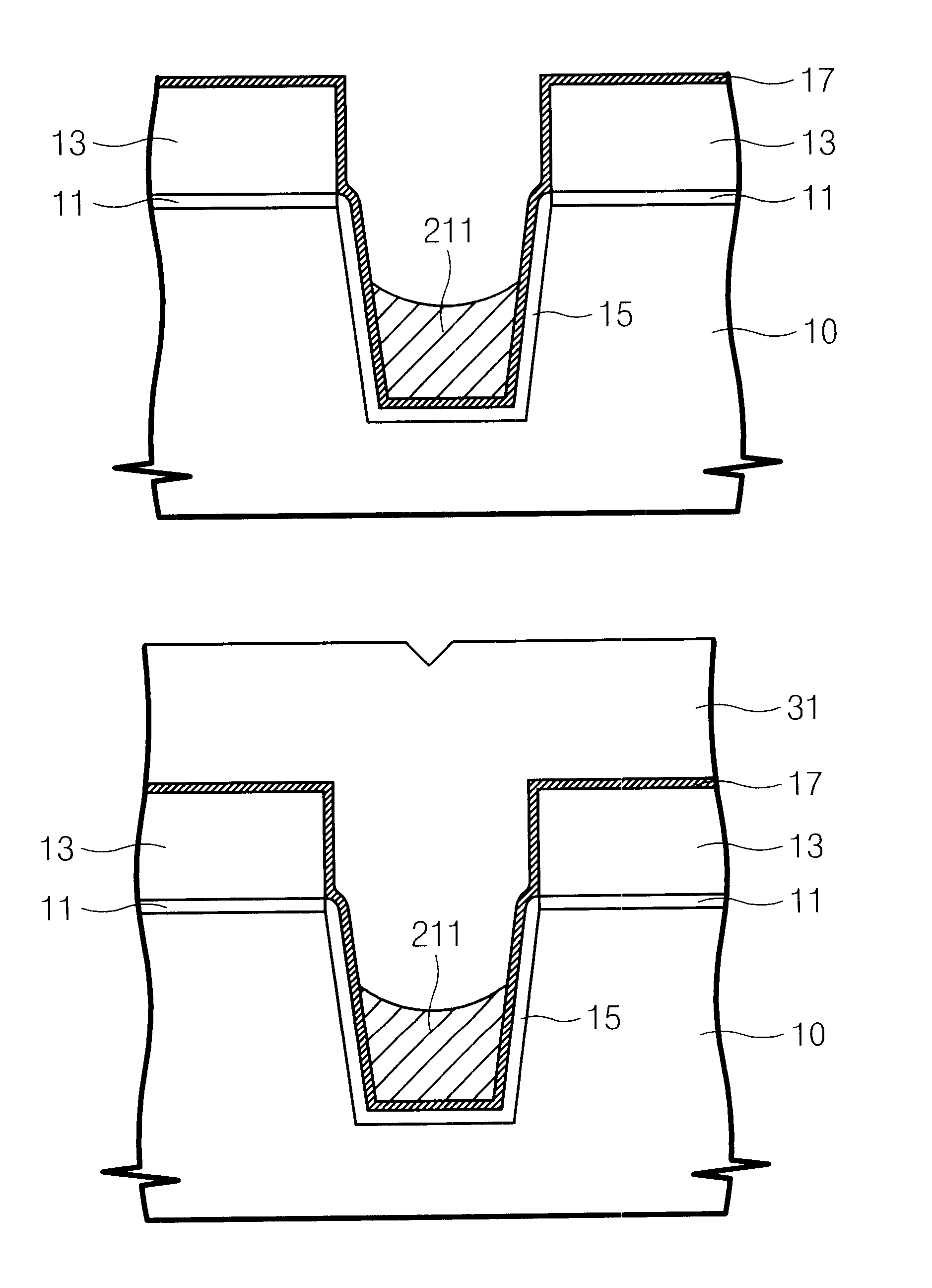
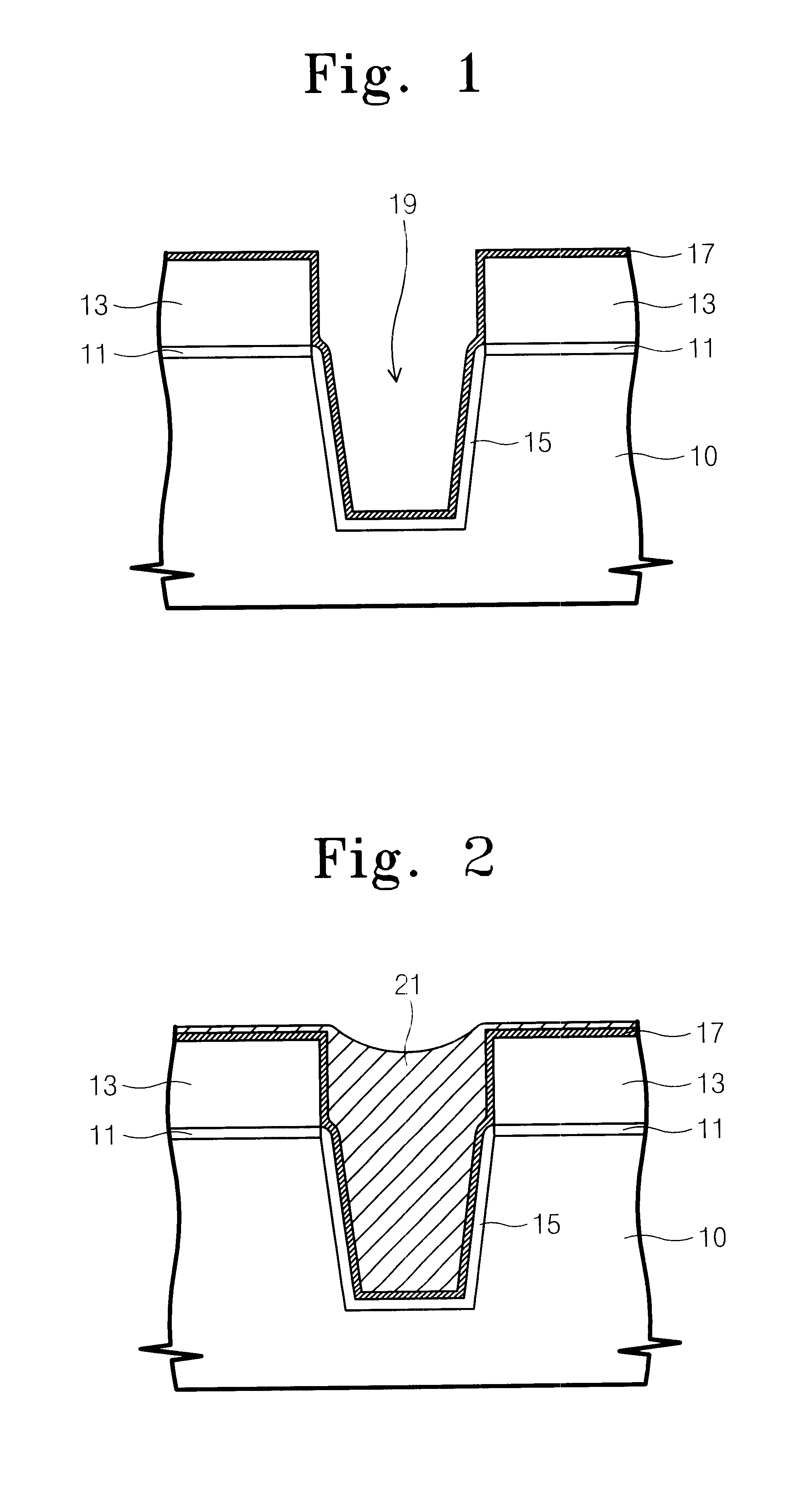
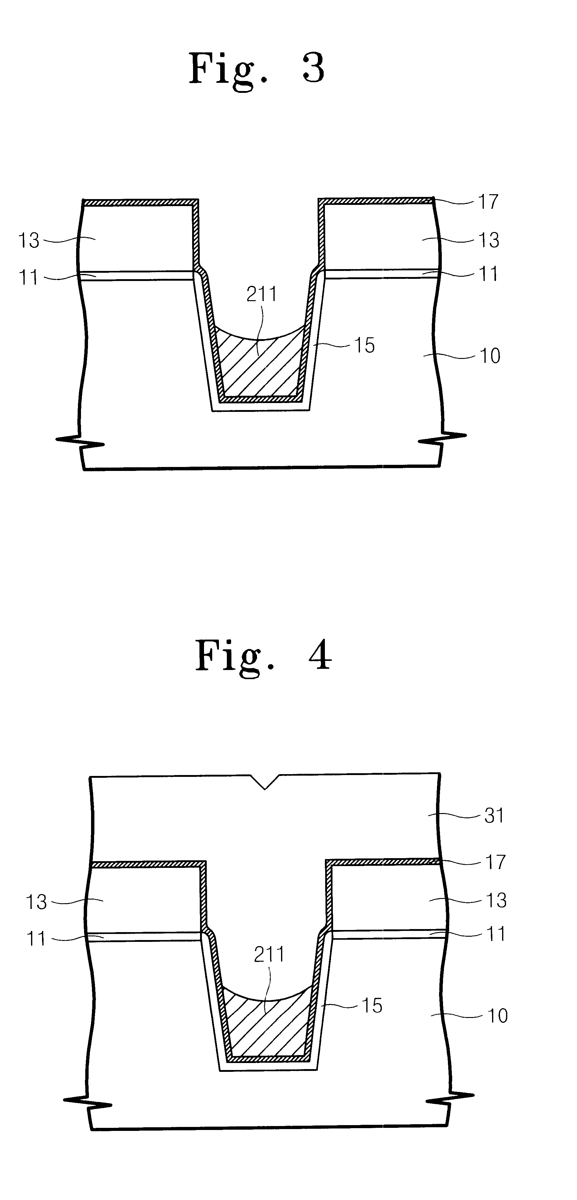
Referring to FIG. 1, a silicon nitride layer (not indicated) is stacked on a semiconductor substrate 10 on which a pad oxide layer 11 is formed. Using a photoresist (not shown), the silicon nitride layer is patterned to form a trench etch mask pattern 13 through exposure and etch steps. Using the trenc...


PUM


Abstract

A method of forming a trench-type device isolation layer in which a trench is filled through two steps, wherein a polysilazane solution is coated on a semiconductor substrate, in which a trench for device isolation layer is formed, in a spin on glass (SOG) manner to form an SOG layer filling a predetermined portion of the trench. In order to maintain a conformal coating thickness without overfilling the trench, the polysilazane solution preferably has a solid-state perhydro polysilazane ([SiH2NH]n) of between about 5 to about 15 percent by weight. Following formation of the SOG layer, a subsequent annealing process is carried out. The SOG layer is etched to make a top surface of the remaining SOG layer recessed down to a degree of about 1000 Å from an inlet of the trench, and a remaining space of the trench is filled with an ozone TEOS USG layer or an HDP CVD layer.

Description

1. Field of the InventionThe present invention relates to a method of forming a device isolation layer in a semiconductor device and, more particularly, to a method of forming a trench-type device isolation layer using an SOG (spin on glass) layer.2. Description of Related ArtAs the integration level of semiconductor devices increases, shallow trench isolation (STI) type device isolation layers are increasingly being used. In a device isolation method employing STI, an oxide layer fills a trench that is formed by etching a semiconductor substrate. The STI technique is used to avoid a "bird's beak" phenomenon resulting from a conventional technique such as local oxidation of silicon (LOCOS).However, an aspect ratio rises rapidly with the trend toward large scale integration circuits (LSI). In other words, a width of a trench to be filled with a device isolation layer decreases while a depth thereof is maintained at the same level. This arrangement makes it necessary to fill up a tren...

Claims


Application Information

Patent Timeline
Patent Type & Authority Patents(United States)
IPC IPC(8): H01L21/762H01L21/70H01L21/76
CPCH01L21/76224H01L21/76
Inventor HONG, SOO-JINPARK, MOON-HANGOO, JU-SEONHEO, JIN-HWAKIM, HONG-GUNHONG, EUN-KEE
Owner SAMSUNG ELECTRONICS CO LTD
Why Eureka
Try Eureka