

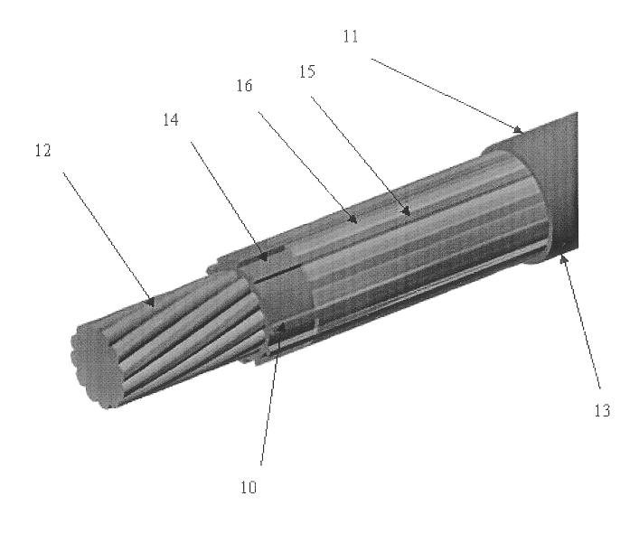
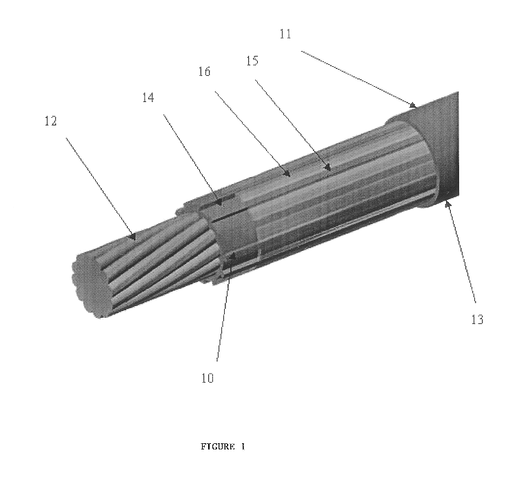
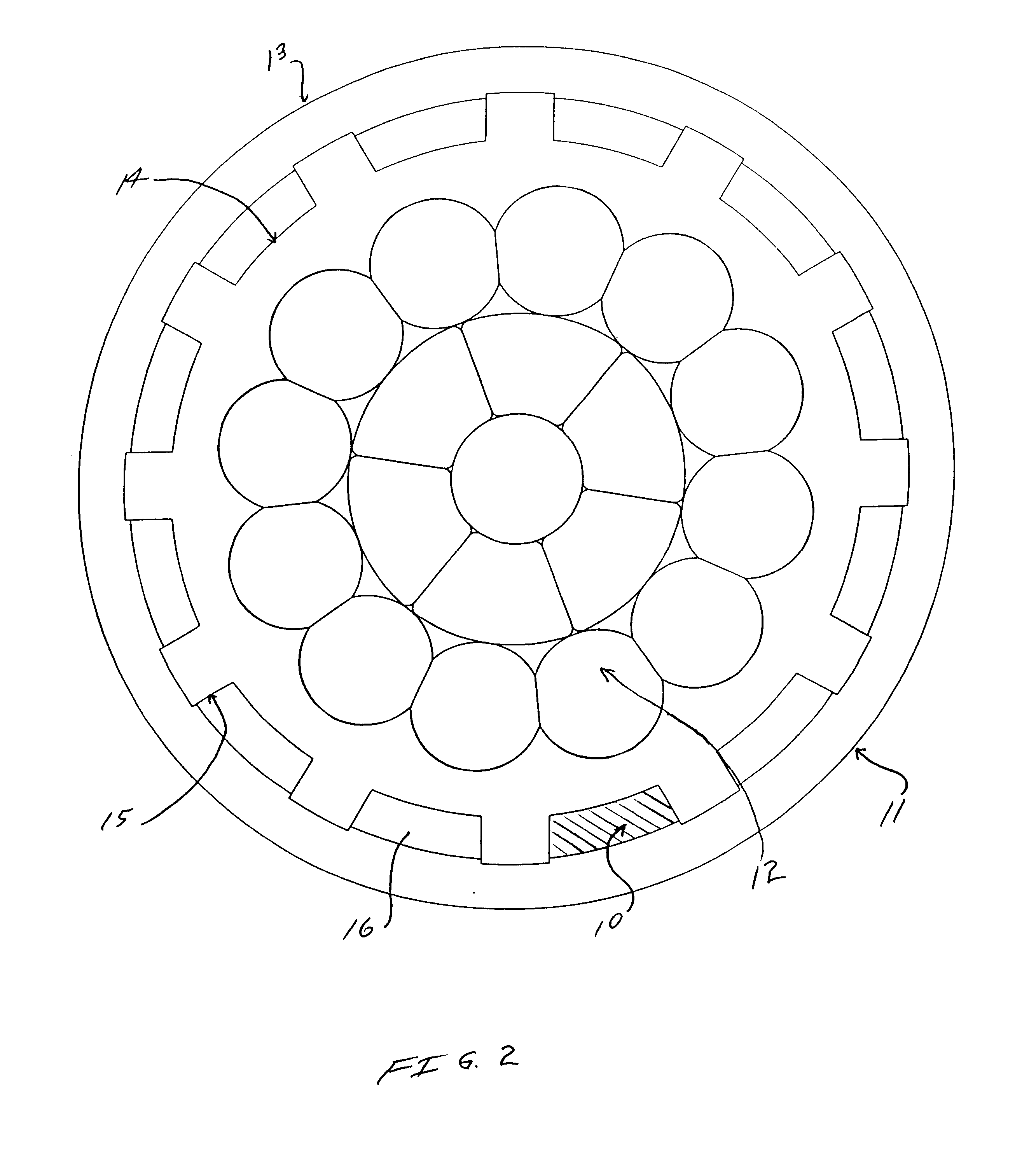
Self-sealing electrical cable having a finned inner layer
a self-sealing, electrical cable technology, applied in the direction of insulated conductors/cables, cables, insulated conductors, etc., can solve the problems of direct buried aluminum secondary cables, alternating current corrosion of aluminum, and puncture in insulation, so as to prevent moisture migration
- Summary
- Abstract
- Description
- Claims
- Application Information
AI Technical Summary
Problems solved by technology
Method used
Image

Examples
example 1
This test was designed to evaluate the performance of the present invention's self sealing, 600 V underground cable. The test program was patterned after a previously developed procedure to evaluate self-sealing or self-repairing cable designs.
To conduct the test damaged cables were placed in a specially mixed, moist soil. The cables were then energized with 120 V ac to ground. Measurements made included changes in leakage current to earth and cable conductor resistance. The temperature of each cable near the damage point was also monitored.
Four control sample replicates and eight self-sealing sample replicates were evaluated. All four control samples failed the test relatively early in the test program. All eight self-sealing samples performed well, with no significant increase in conductor resistance and low leakage current values throughout the 60-day test period.
Conventional and self-sealing 600 volt underground cable with a 2 / 0 AWG combination unilay aluminum conductor were tes...
example 2
A cyclic load test was run on the finned cable of the present invention and compared with similar non-finned prior art cables. 50 ft. samples were tested. The samples had a 50.degree. C. conductor temperature, and were cycled on 8 hours a day and off 16 hours, 7 days a week. The cables were terminated with a mechanical connector. No duct seal, mastic tape, electrical tape, or the like was used. The tops of the samples were approx. 11 ft. above the floor. The samples gradually droop to the floor.
Shrinkback Total Weeks of Aging Shrinkback at Top at Bottom Shrinkback (in) Sample 1 (Invention) Initial .0000 .0000 .0000 1 .3035 .1510 .4545 Sample 2 (Invention) Initial .0000 .0000 .0000 1 .1385 .1880 .3265 Sample 1 - Bare (Prior Art) Initial .8450 .2220 1.0670 4.6375 1.2010 5.8385 5.5390 .8220 6.3610 5.9350 .6735 6.6085 6.1110 .6150 6.7260 5.9065 .5850 6.4915 6.3725 .6020 6.9745 6.2960 .7320 7.0280 6.4500 .5340 6.9840 6.6855 .4350 7.1205 Sample 2 - Duct Seal (Prior Art) Initial .2205 .255...
PUM
| Property | Measurement | Unit |
|---|---|---|
| thickness | aaaaa | aaaaa |
| impulse breakdown | aaaaa | aaaaa |
| water temperature | aaaaa | aaaaa |
Abstract
Description
Claims
Application Information