Voltage-boosting generator for reducing effects due to operating voltage variation and temperature change

a voltage-boosting generator and operating voltage technology, applied in the field of voltage-boosting generators, can solve the problems of reducing the boosting capacity provided by the voltage-boosting generator, affecting the operation of the voltage-boosting generator, and changing the voltage detected by the voltage-detecting circui

Inactive Publication Date: 2003-06-17
MACRONIX INT CO LTD
View PDF4 Cites 17 Cited by
  • Summary
  • Abstract
  • Description
  • Claims
  • Application Information

AI Technical Summary

Benefits of technology

Accordingly, one object of the present invention is to provide a voltage-boosting generator capable of reducing operating voltage and temperature effect. As the operating voltage and temperature of a die changes, the voltage-boosting generator has an automatic mechanism for adjusting the charging time and the number of conductive voltage-driving MOS transistors so that the effects produced by the ch

Problems solved by technology

However, if there is a change in the operating voltage or the temperature of the die, voltage detected by the voltage detecting circuit may also change.
ng time. On the contrary, a smaller charging output from the voltage-boosting generator results in a longer chargin
g pe

Method used


Image

  • Voltage-boosting generator for reducing effects due to operating voltage variation and temperature change
  • Voltage-boosting generator for reducing effects due to operating voltage variation and temperature change
  • Voltage-boosting generator for reducing effects due to operating voltage variation and temperature change

Examples


Embodiment Construction

Reference will now be made in detail to the present preferred embodiments of the invention, examples of which are illustrated in the accompanying drawings. Wherever possible, the same reference numbers are used in the drawings and the description to refer to the same or like parts.

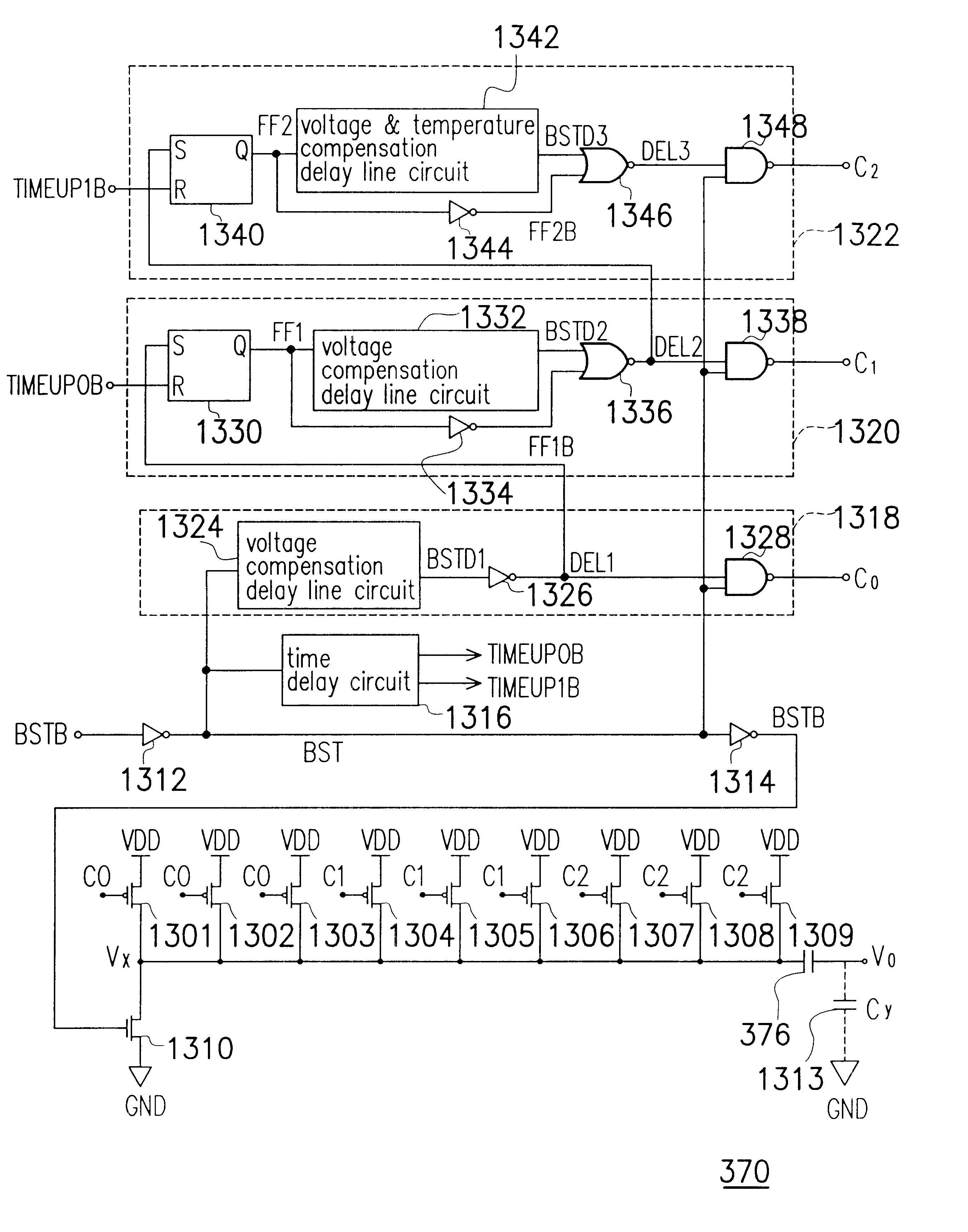
FIG. 3 is a block diagram of a voltage-boosting generator according to a preferred embodiment of this invention. As shown in FIG. 3, a delay line circuit 372 inside a voltage-boosting generator 370 receives a initial boosting (BST) signal. After a period of delay, the delay line circuit 372 transmits out a control signal to a voltage-boosting circuit 374 in order to charge a capacitor 376. After the capacitor 376 is charged by the voltage-boosting circuit 374, an output voltage Vo is risen to a voltage value that is required for the operation.

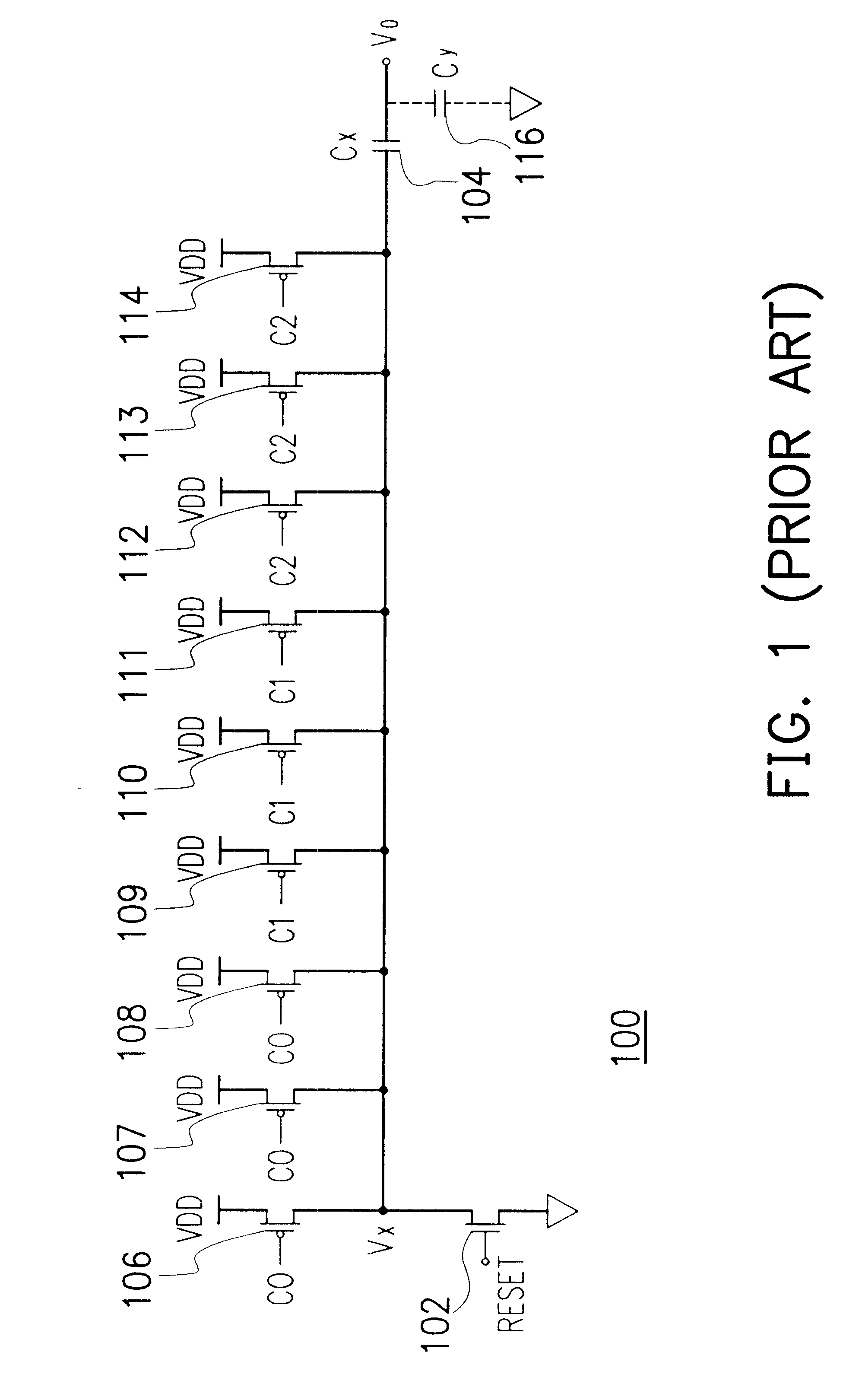
The voltage-boosting circuit 374 can be integrated by a plurality of metal oxide semiconductors (MOS) (shown in FIG. 1). The voltage-boosting circuit 374 further comp...


PUM


Abstract

A voltage-boosting generator for reducing the effects due to operating voltage variation and temperature change. The generator comprises a delay line circuit and a voltage boosting circuit. The delay line circuit is used to perform a time delay according to an initial boosting signal and to produce a control signal. The voltage boosting circuit is used to boosted voltage according to the control signal.

Description

CROSS-REFERENCE TO RELATED APPLICATIONThis application claims the priority benefit of Taiwan application serial no. 90123430, filed Sep. 24, 2001.BACKGROUND OF THE INVENTION1. Field of InventionThe present invention relates to a voltage-boosting generator. More particularly, the present invention relates to a voltage-boosting generator for reducing the effects due to operating voltage variation and temperature change.2. Description of Related ArtDue to rapid progress in semiconductor manufacturing technologies, the number of transistors in each die is forever increasing. Consequently, stability of circuit during operation must be considered. For example, the voltage-boosting generator for providing suitable operating voltage to the circuit must consider factors such variation of operating voltage, temperature effects and so on.FIG. 1 is a circuit diagram of a conventional voltage boosting circuit. When the voltage-boosting generator 100 is not in an operating mode, the gate terminal...

Claims


Application Information

Patent Timeline
IPC IPC(8): H02M3/04H02M3/07
CPCH02M3/07
Inventor HSU, HSIEN-WENLIN, YU-SHENHUNG, CHUN-HSIUNGLIOU, HO-CHUN
Owner MACRONIX INT CO LTD
Why Eureka
Try Eureka