
Heater sealed with carbon wire heating element

a heating element and carbon wire technology, applied in the field of heating elements sealed with carbon wire heating elements, can solve the problems of unstable heating element performance, affecting the performance of heating elements, and difficulty in properly adjusting various physical properties including resistan

Inactive Publication Date: 2003-06-24
COORSTEK INC +1
View PDF12 Cites 19 Cited by
  • Summary
  • Abstract
  • Description
  • Claims
  • Application Information

AI Technical Summary

Benefits of technology

The solution provides a heater with stable resistance and enhanced anti-aging characteristics, preventing changes in physical properties like electric resistance, even at high temperatures, and allowing for fine adjustment of resistance uniformity.

Problems solved by technology

Recently, however, it was recently observed that said conventional carbon wires for the heating element were often used at a temperature higher than the prescribed temperature needed for firing and the disadvantage that the heater performance such as electric resistance thereof or the like becomes unstable has been pointed out.
2 The chemicals adhered to the carbon wires are liberated by the heat in the form of a gas to change the inner pressure inside the quartz glass member filled with the carbon wires during the long service life thereof with the result that the performance of the heating element is affected.
On the other hand, the graphitization will not fully proceed at a temperature less than 2000.degree. C. with the result that it is difficult to properly adjust various physical properties including the resistance thereof (.OMEGA. / m).
With carbon single fibers having a diameter of less than 5 .mu.m, the toughness of each single fiber is so insufficient that it is difficult to manufacture a heating element by binding and knitting a plurality of single fibers into a demanded elongate form.
Moreover, since each single fiber is too fine, the number of single fibers needed to acquire a predetermined number of resistance is too large to be put to a practical use.
On the other hand, a single fiber having a diameter exceeding 15 .mu.m lacks elasticity, making it difficult to knit binds of single fiber.
If, however, an excessively large number of bundles are used in the preparation of a carbon wire, knitting is difficult.
It is also rather difficult to obtain a preferable finish in shape because the knitted product can fray when broken in part.
If the number of fibers is more than 6000 on the other hand, the number of fiber bundles prepared by binding said single fibers is too small to obtain a predetermined resistance, making it difficult to maintain a required shape of the carbon wire prepared by knitting.

Method used


Image

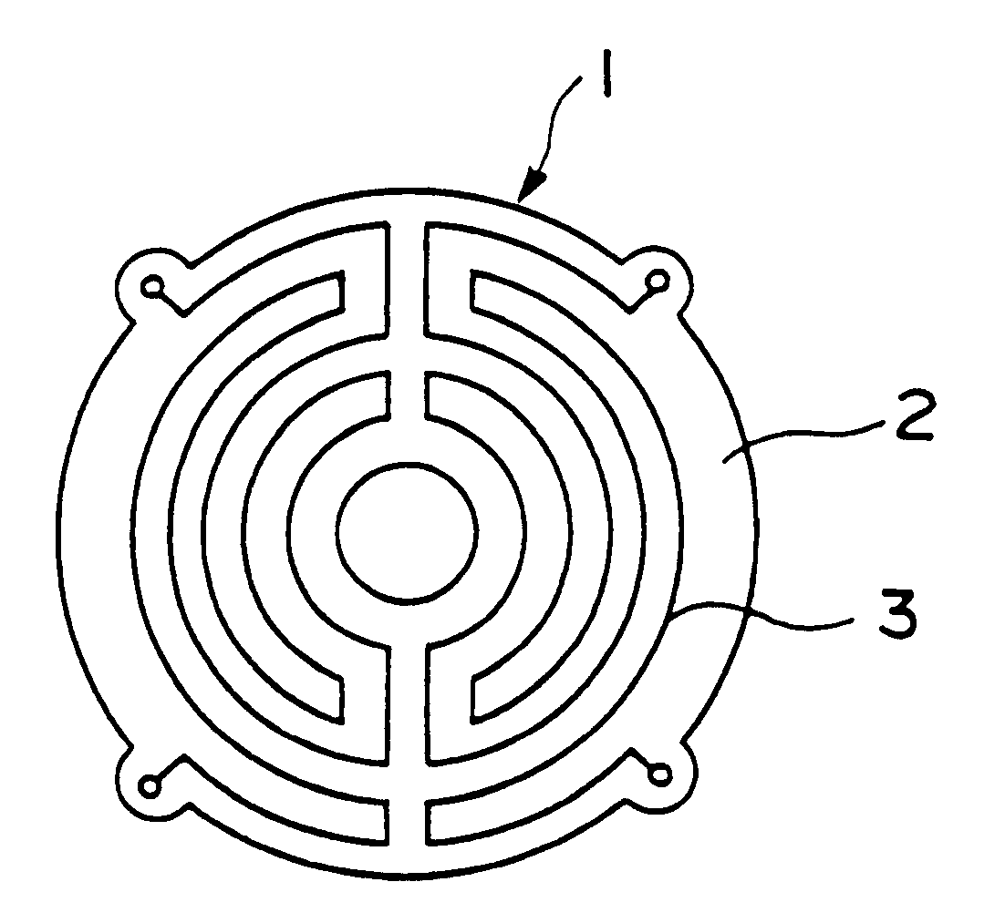
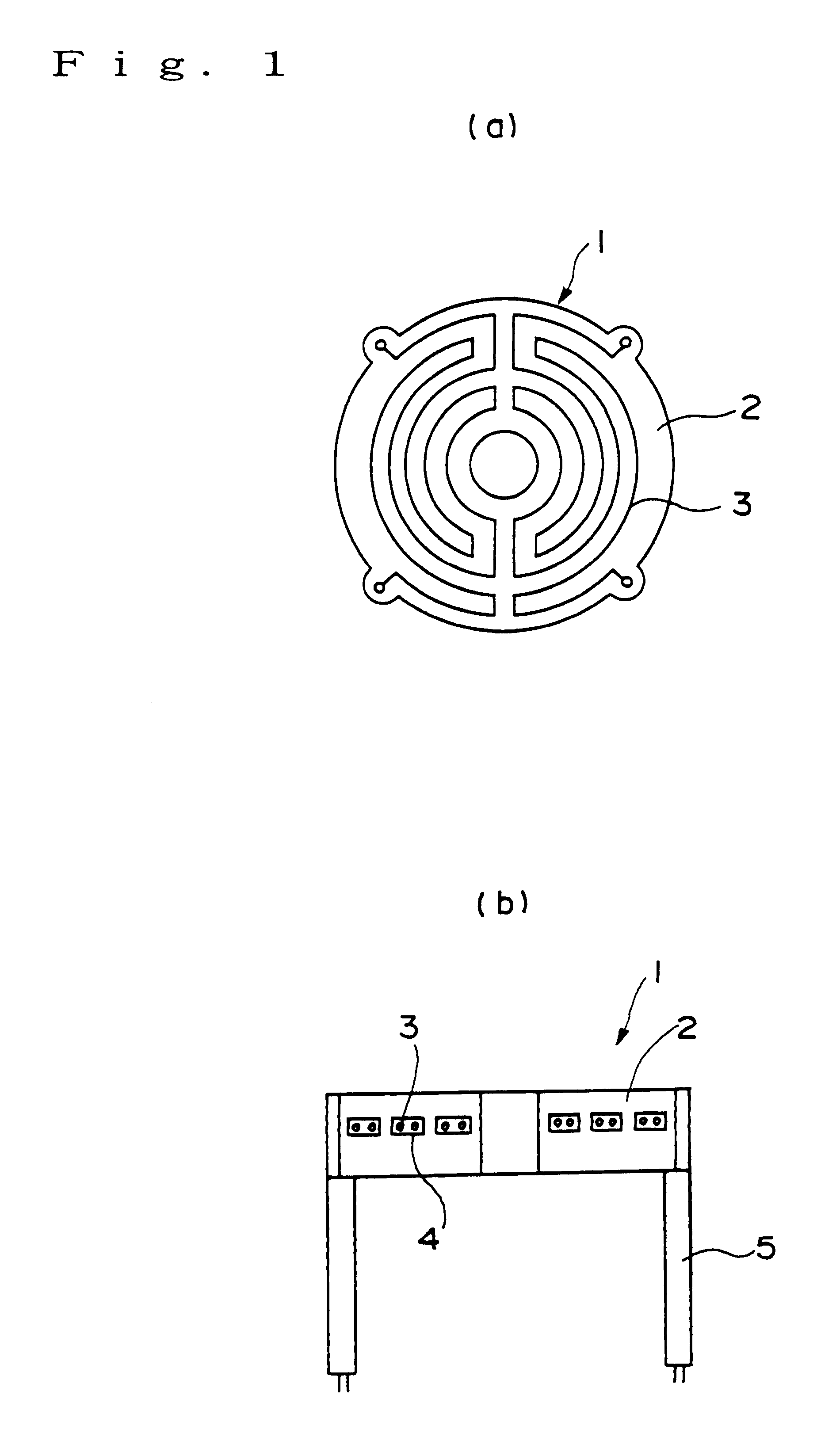
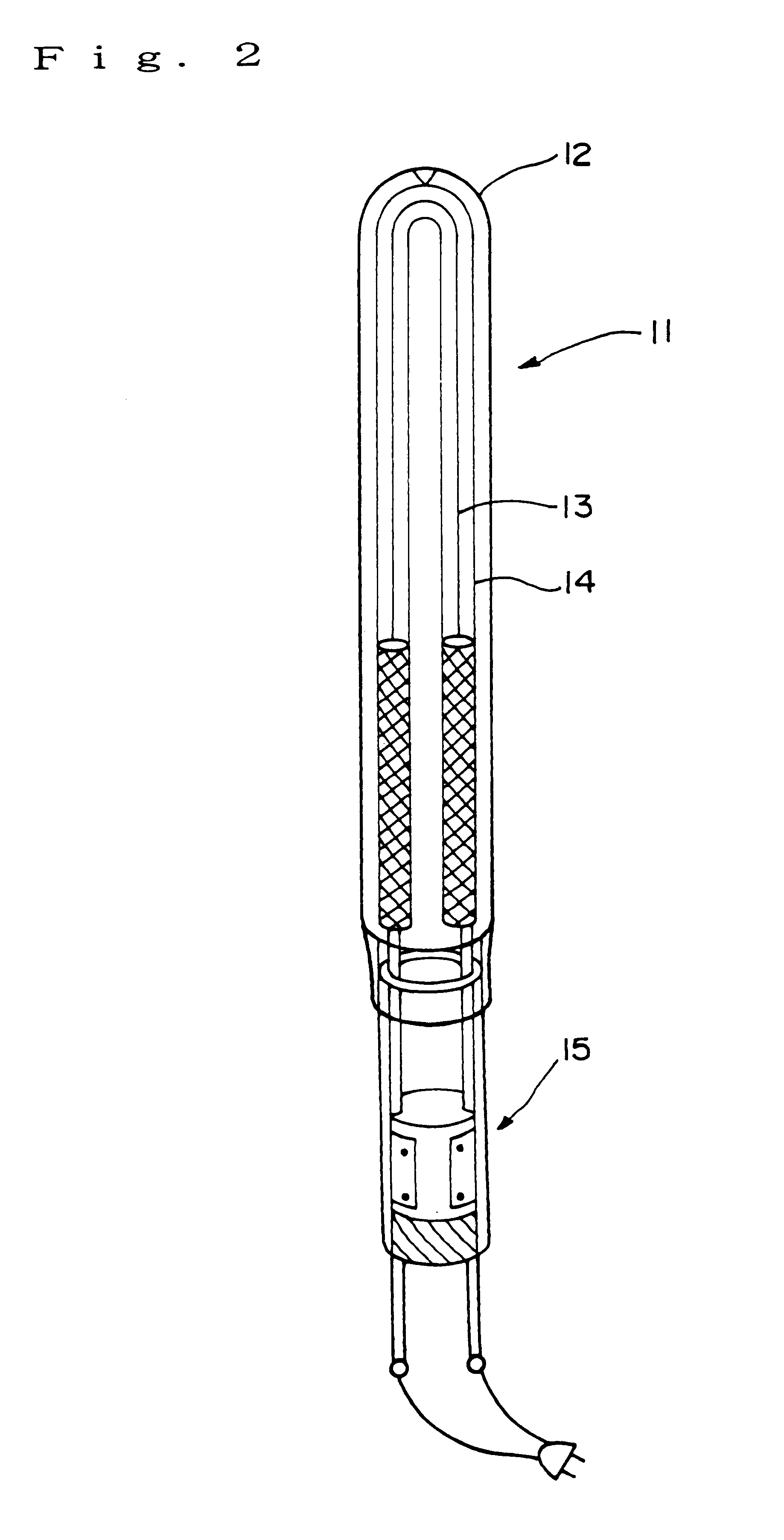
  • Heater sealed with carbon wire heating element
  • Heater sealed with carbon wire heating element
  • Heater sealed with carbon wire heating element

Examples


Embodiment Construction

Then, carbon wires are prepared by binding 3000 pieces of various carbon single fibers (including one PAN-based carbon fiber and one pitch-based carbon fiber) each having a diameter of 7 .mu.m into a bundle and knitting 9 such bundles into a knitted cord having a diameter of 2 mm. (each carbon wire having a length of 100 meters)

Among said carbon wires, those of each selected type are subjected to a graphitization process at a temperature of 2300.degree. C. in an argon gas atmosphere (0.01 Torr) in a heat treatment reactor.

The thus graphitized various types of carbon single fibers and untreated such various types of carbon single fibers are selected to measure their interlayer spacing d (002) and crystallite size Lc (002) using Gakushin-method.

The result obtained is shown in Table 1.

Further, the graphitized PAN (polyacrylonitrile) type carbon wires and untreated counterparts are respectively subjected to measurement for respective electric resistances thereof (5 times for each type) ...


PUM

PropertyMeasurementUnit
crystallite size Lcaaaaaaaaaa
elongation performanceaaaaaaaaaa

Abstract

A heater sealed with carbon wire heating element has a carbon wire heating element sealed with a quartz glass member, the carbon wire being prepared by knitting carbon single fibers into a knitted cord of a braid, each wire having a crystal structure with a interlayer spacing d (002) thereof being 0.343 or less and crystallite size Lc (002) thereof being 4.0 nm or more.

Description

1. Field of the InventionThe present invention relates to a heater sealed with a carbon wire heating element therein and more particularly to a heater sealed with a carbon wire heating element in which a carbon wire of carbon fibers having a particular crystal structure is sealed as a heating element, resulting in obtaining a heater sealed with a carbon wire heating element excellent in stable resistance when the current is flowing and particularly in anti-aging characteristic.2. Description of the Related ArtHeaters using a carbon heating element therein have excellent properties in raising and lowering the temperature due to a small heat capacity as compared to heaters using a metal heating element, and offering a wide industrial application to various types of heating apparatus.In the field of the semiconductor manufacturing, especially, silicon wafers are subjected to various heat treatments in the process thereof. Moreover, such heat treatments are in need of strict temperature...

Claims


Application Information

Patent Timeline
Patent Type & Authority Patents(United States)
IPC IPC(8): H01L21/00H05B3/14D04B21/20H05B3/84D04C1/02D04C1/06H01L21/324H05B3/02H05B3/44
CPCH01L21/67103H05B3/145H01L2924/0002H01L2924/00H05B3/40
Inventor SEKO, SUNAOKONN, TOMIONAGATA, TOMOHIROSAITO, NORIHIKOYOKOYAMA, HIDEYUKIKOBAYASHI, MASAKAZUSAITO, TAKANORINAKAO, KEN
Owner COORSTEK INC
Learn More