Method and device for emitting radial seismic waves in a material medium by electromagnetic induction

a technology of electromagnetic induction and radial seismic waves, which is applied in the direction of mechanical vibration separation, survey, borehole/well accessories, etc., and can solve problems such as affecting their efficiency

Inactive Publication Date: 2003-07-22
INST FR DU PETROLE
View PDF8 Cites 30 Cited by
  • Summary
  • Abstract
  • Description
  • Claims
  • Application Information

AI Technical Summary

Problems solved by technology

In the case of cased wells, their efficiency is affected by the stiffn...

Method used


Image

  • Method and device for emitting radial seismic waves in a material medium by electromagnetic induction
  • Method and device for emitting radial seismic waves in a material medium by electromagnetic induction
  • Method and device for emitting radial seismic waves in a material medium by electromagnetic induction

Examples


Embodiment Construction

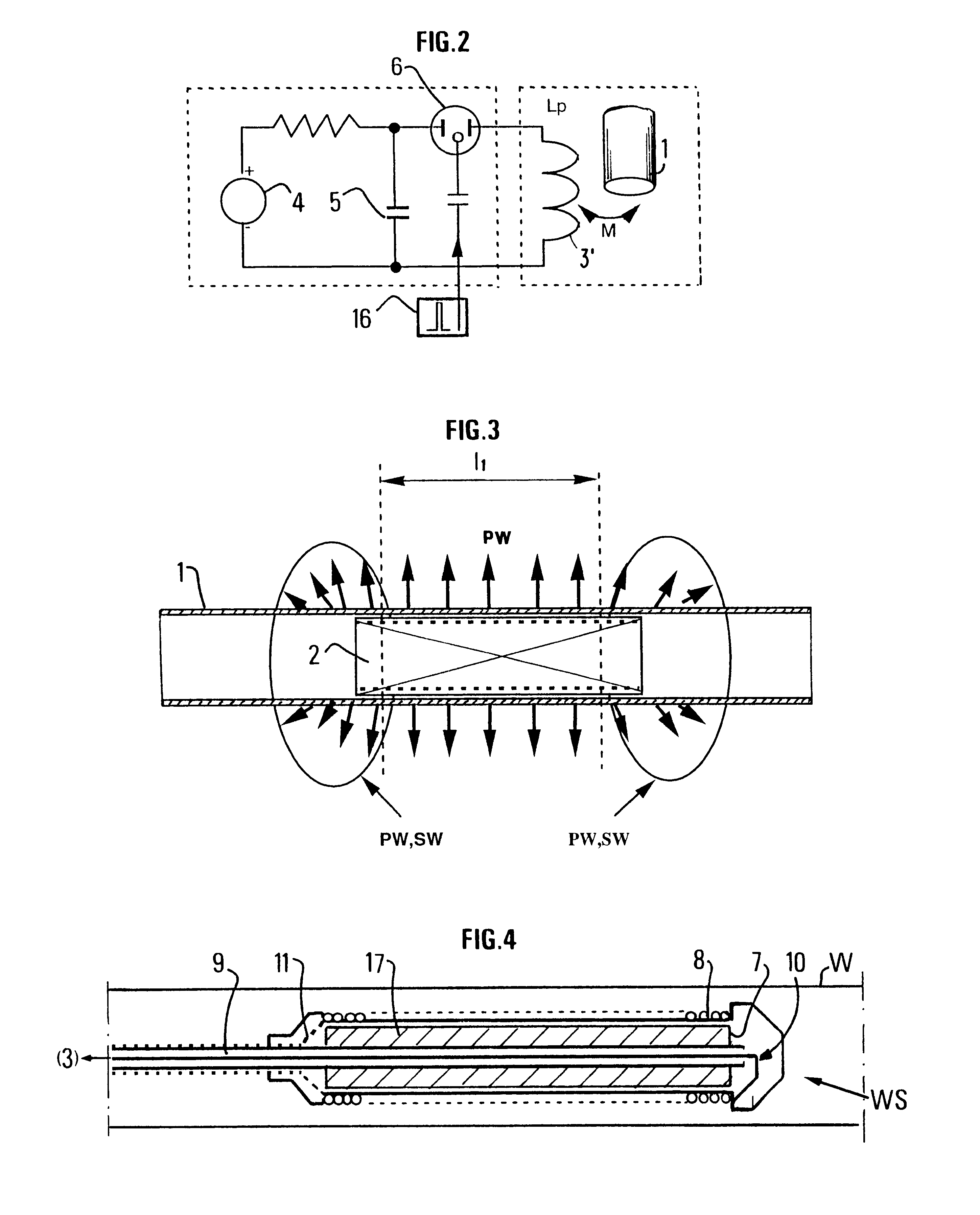
coil was made for a 7-inch casing and a shock generator with a capacitive storage of 1 kJ associated therewith (C=80 .mu.F, V=5 kV). The coil, which was 145 mm in mean diameter (150 mm in overall diameter) comprised 200 turns in a single layer over a length of 1 m. The resistance of the loop consisting of 1 m of the casing was of the order of 10.sup.-4.OMEGA..

FIGS. 5 and 6 respectively show the shape of the signal at the output of the electric shock generator and that of the current circulating in the tube or casing. The pulse has a waveform close to the one desired at critical damping. The current peak is of the order of 300 kA, which gives a pressure peak of the order of 60 kPa.

The emitted seismic signal measured by a geophone in a well 5 m above the source is shown in FIG. 7. Its spectrum is in accordance with that of the electric pulse with a maximum amplitude in the vicinity of 600 Hz (FIG. 8).

Variants

In order to improve the efficiency of the source, the axial magnetic field ca...


PUM


Abstract

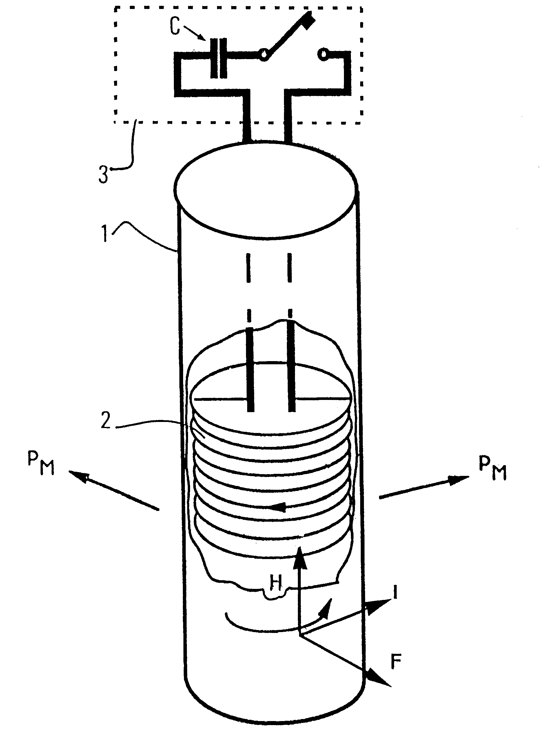
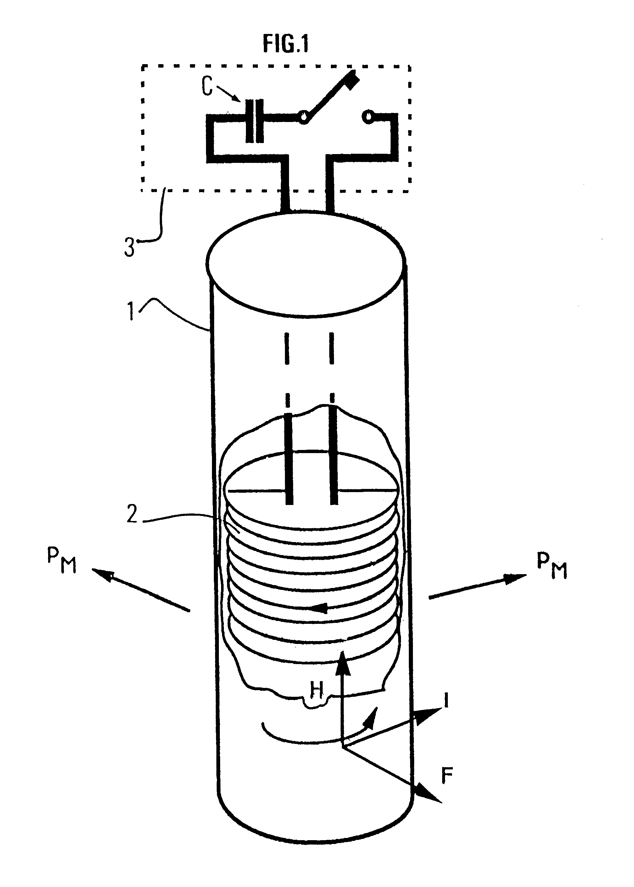
A method and device for emitting radial seismic waves in a material medium by electromagnetic induction, used notably for generating seismic waves in cased or uncased wells or in a water mass is disclosed. Emission of radial waves is essentially obtained by radially expanding a metal tube (1) under the effect of a magnetic pressure generated by electromagnetic induction with elastic waves being created in the medium under the effect of this expansion. The magnetic pressure is obtained by connecting a coil (2) in line with the tube to a current generator (3). The winding pitch of coil (2) can be constant or variable. Tube (1) can for example be added into a well or hole or it can be a tube portion of a cased well.

Description

1. Field of the InventionThe present invention relates to a method and to a device for emitting radial seismic waves in a material medium such as the subsoil, by electromagnetic induction, used notably for generating seismic waves in cased wells or in a water body.2. Description of the Prior ArtThere are different types of seismic sources suited to emit in wells. They involve:explosions: a point or an elongated charge or detonating cord helically wound on a rigid spindle,electric sparks (a breakdown between electrodes in water or wire explosion under the effect of an electric discharge, etc.),vertical mechanical shock of a mass falling or thrown onto an anvil secured to a packer, which produces a vertical shear on the well wall mainly generating S waves,or a horizontal shock, in a radial direction, of a mass radially driven by hydraulic or electromagnetic device and that strikes the wall of the well at one point.Controlled vibrational sources of piezoelectric or magnetostrictive typ...

Claims


Application Information

Patent Timeline
IPC IPC(8): G01V1/02G01V1/52G01V1/04G01V1/40G10K9/12G10K9/00
CPCG01V1/02G01V1/04G01V1/52G10K9/12
Inventor DUBOIS, JEAN-CLAUDEMEYNIER, PATRICK
Owner INST FR DU PETROLE
Why Eureka
Try Eureka