Aluminum-coated plastic member

Inactive Publication Date: 2003-07-22
LUK LAMELLEN & KUPPLUNGSBAU BETEILIGUNGS KG
View PDF12 Cites 28 Cited by
  • Summary
  • Abstract
  • Description
  • Claims
  • Application Information

AI Technical Summary

Benefits of technology

Still another object of the present invention is to provide a novel and improved actua

Problems solved by technology

The aforementioned publication fails to disclose or suggest the possibility of producing films or layers of aluminum or an aluminum alloy on shaped plastic articles for the purpose

Method used


Image

  • Aluminum-coated plastic member
  • Aluminum-coated plastic member

Examples


Embodiment Construction

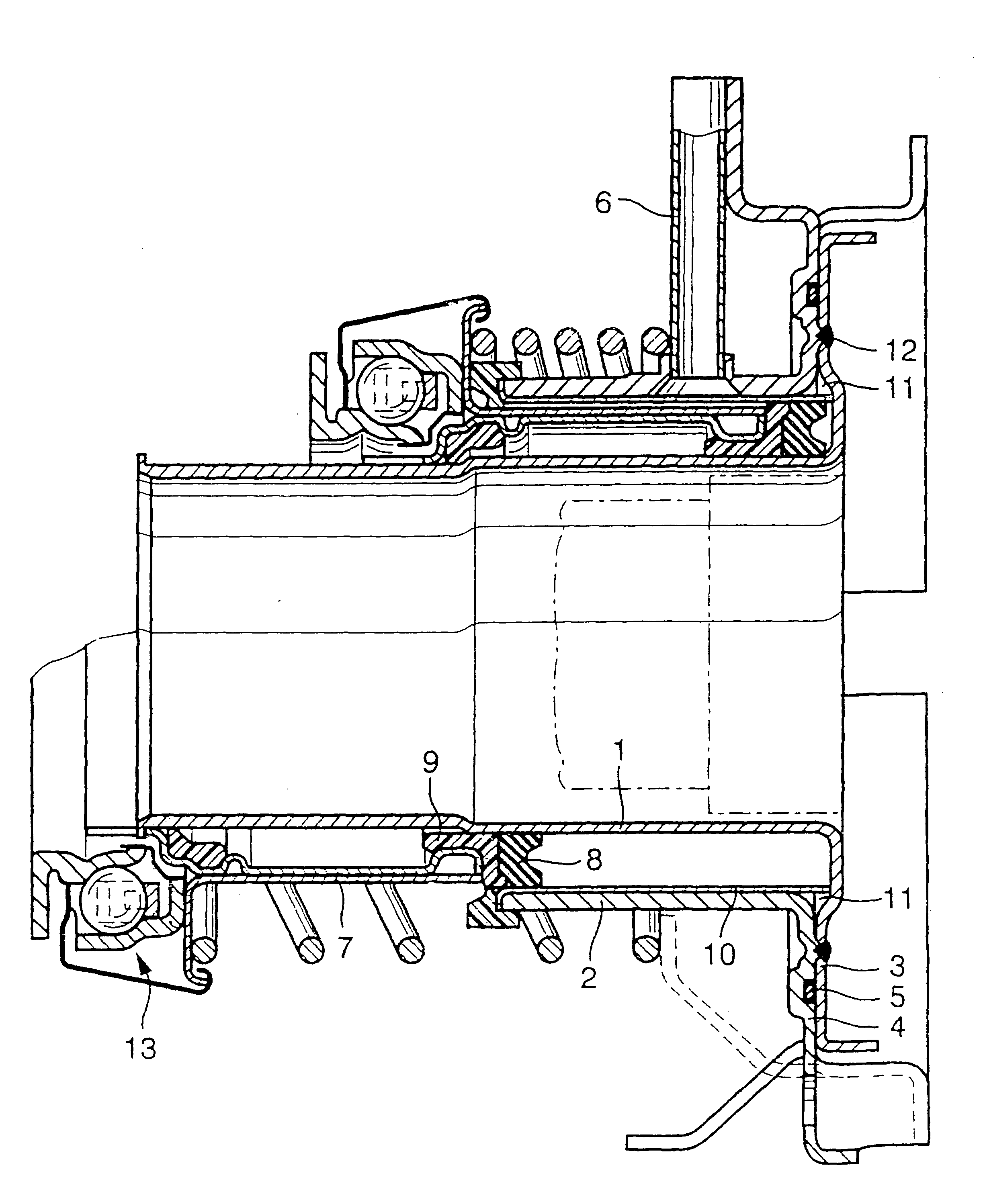
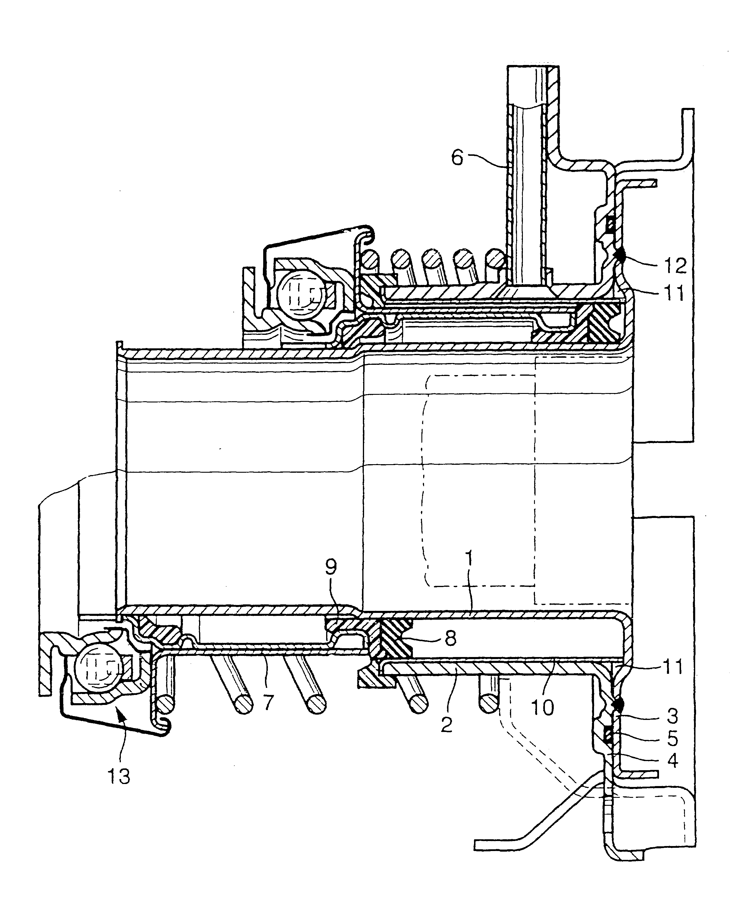
The drawing shows a portion of a hydraulically operated clutch engaging-disengaging unit wherein a composite cylinder includes a radially inner cylindrical wall 1 and a concentric radially outer cylindrical wall 2. These walls are made of a suitable metallic sheet material and are respectively provided with radially outwardly extending annular flanges 3 and 4 partially overlying each other and being bonded to one another by at least one circumferentially complete welded seam 12 or by an annular array of discrete spot welds. The reference character 5 denotes a resilient sealing element which is recessed into an annular groove at the outer side of the flange 4.

The cylinder including the parts 1, 2, 3, 4 and 12 receives a reciprocable hollow piston 7 which, in the illustrated embodiment, is made of suitable metallic sheet stock. The front end face of the piston 7 carries a sealing ring 8 having a grooved front side and being movable back and forth in the annular space between the walls...


PUM

PropertyMeasurementUnit
Temperatureaaaaaaaaaa
Densityaaaaaaaaaa

Abstract

A composite part of a clutch for use in a motor vehicle has a plastic carrier and a film of oxidized aluminum or an aluminum alloy overlying and adhering to that part of the carrier which is in sliding contact with at least one other part of the clutch. Oxidizing of the film is the result of a chemical or electrochemical treatment.

Description

The invention relates to improvements in methods of enhancing certain properties of parts which are made of a plastic material. The invention also relates to processed plastic parts which have undergone a treatment in accordance with the improved method. More particularly, the invention relates to improvements in parts of the type wherein a plastic carrier is coated, at least in part, with a film of aluminum or an aluminum alloy.The German-language book entitled "Kunststoff-Me-tallisieurung" (meaning "Metallizing of Synthetic Plastic Materials"), published in 1991 by Eugen G. Leuze Verlag, Saulgau / Wdrttemberg, Federal Republic Germany, discloses (on page 75) a computer housing which is made of a plastic material and is provided with a layer of aluminum for the purpose of limiting the amount of electromagnetic radiation issuing from the computer. Page 83 of the same publication discloses the coating of polyester or polycarbonate foils with aluminum films. The purpose of such films is...

Claims


Application Information

Patent Timeline
IPC IPC(8): C25D11/18C25D11/24C25D11/04C23C8/02C23C28/00F16D25/08C08J7/04C23C14/20C23C14/58C25D11/00
CPCC23C8/02C25D11/04C25D11/24C25D11/243F16D25/083C25D11/08C25D11/16C25D11/18
Inventor VENZ, RAINER
Owner LUK LAMELLEN & KUPPLUNGSBAU BETEILIGUNGS KG
Why Eureka
Try Eureka