Method of producing a crystal sheet, apparatus for use in producing the same, and solar cell

a technology of crystal sheets and apparatus, applied in the direction of crystal growth process, polycrystalline material growth, protective fluid, etc., can solve the problems of silicon inconvenient, cost-intensive steps, and loss of silicon source material

Inactive Publication Date: 2003-07-22
SHARP KK
View PDF20 Cites 39 Cited by
  • Summary
  • Abstract
  • Description
  • Claims
  • Application Information

AI Technical Summary

Problems solved by technology

However, the slicing step is costly and cutting a portion results in a loss of the source material of silicon.
Such silicon is inconvenient if it is used as a substrate of a solar cell as the substrate is required to be flat in a process step such as screen-printing an electrode, laminating, vacuum-chucking and the like.
Furthermore, a conventional substrate tray provided to be suitable for a flat substrate, cannot be used.
Current temperature controlling systems, however, would not satisfactorily respond in proportion to crystal-growth rate in general.
As a result, the crystal sheet is disadvantageously required to grow at a reduced rate.
As such, an enormous load is imposed on the silicon ribbon and thus tends to damage the silicon ribbon.
Furthermore, if a silicon ribbon is damaged extracting it can not immediately be resumed and it can thus hardly be reliably successively extracted.
Furthermore, in the conventional methods, it is difficult to control an in-plane temperature profile of a crystal sheet and it is thus necessary to consider thermal conductivity and the like in selecting a material for a substrate and a member therearound and also to optimize a heating portion such as a heater or a cooling portion in arrangement and geometry.
As such, the temperature profile can hardly be optimized.
Furthermore, it is often difficult technically as well as mechanically to optimize the heating portion and the cooling portion for both of the quality of the crystal of the crystal sheet and the removability thereof.
In particular, removability is a parameter significantly depending on the material(s) of the substrate and precise control can thus hardly be achieved.
As such, it is difficult to produce a crystal sheet of high quality successively and reliably.
Furthermore, preferably, the movable member and the plate are unleveled to allow them to be fit into each other.
In particular, a melt of silicon has a high temperature and is also highly reactive and it is thus extremely difficult to select a material for the members, as appropriate.
If a substrate has a flat surface it is difficult to control a point at which a crystal nucleus is created and other conditions for growing a crystal sheet, e.g., the temperature to be set, the rate at which the substrate is cooled, and the like, need to be controlled to control a point at which a crystal nucleus is created.
As such, dendrite growth tends to be dominant, resulting in a growing crystal sheet being increasingly unleveled.
This reduces the durability of substrate 130 for continuous use.
The first protrusion has a low level of mechanical strength for high temperature.

Method used


Image

  • Method of producing a crystal sheet, apparatus for use in producing the same, and solar cell
  • Method of producing a crystal sheet, apparatus for use in producing the same, and solar cell
  • Method of producing a crystal sheet, apparatus for use in producing the same, and solar cell

Examples


sixth examples

THIRD TO SIXTH EXAMPLES

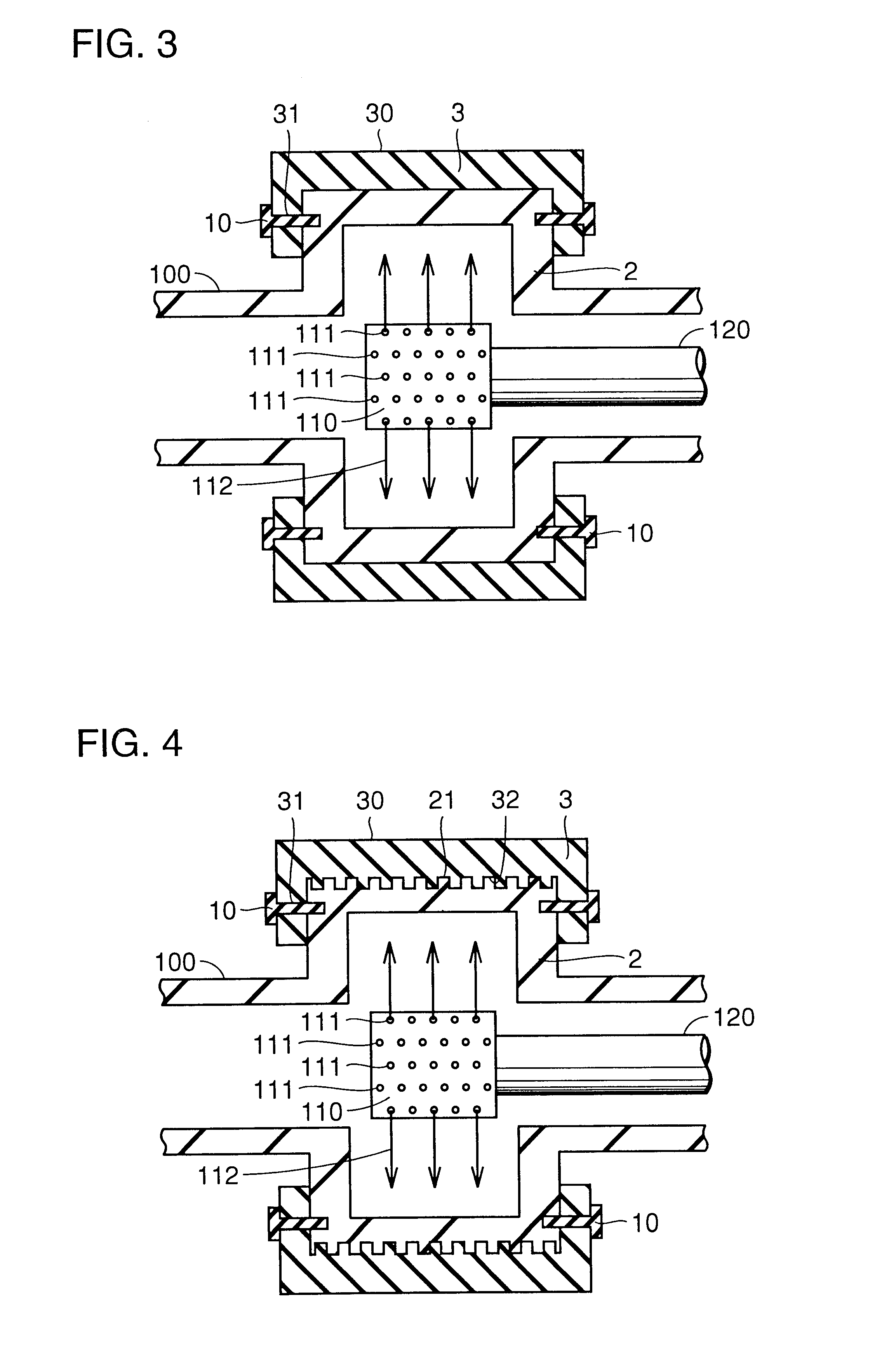
Third to sixth examples are provided in a manner similar to that as employed in the first embodiment, except that substrate 3 has an unleveled surface. More specifically, the third example employs the FIG. 20 substrate 3. The fourth example employs the FIG. 21 substrate. The fifth example employs the FIG. 22 substrate. The sixth example employs the FIG. 23 substrate. Each substrate has a recess of 1 mm in pitch and 1 mm in depth. In FIGS. 22 and 23, planar protrusion 3d is 5 mm wide. Each substrate 3 is employed to fabricate a solar cell, which exhibits characteristics, as shown in Table 1.

seventh example

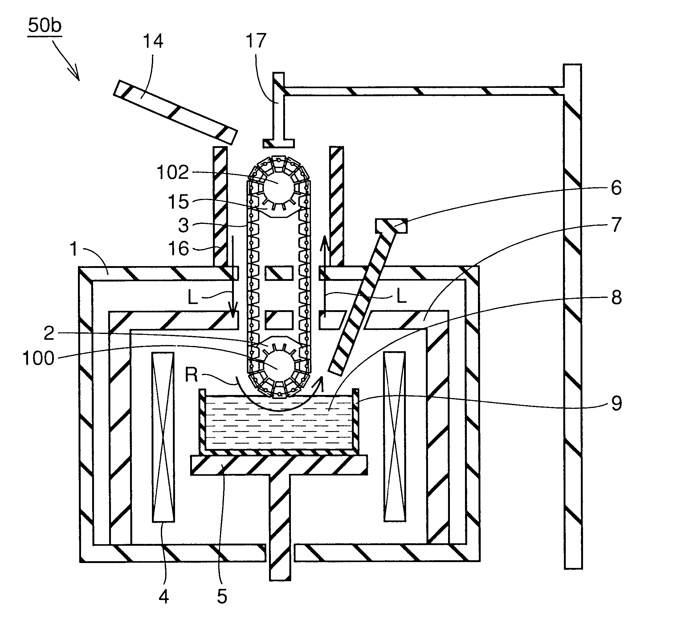
Initially, a source material of silicon is prepared with boron having a concentration adjusted to provide a specific resistance of 2.OMEGA..multidot.cm. The source material of silicon is introduced into a crucible of quartz protected by a crucible of highly pure carbon. The crucible was fixed internal to main chamber 1 shown in FIG. 41. Main chamber 1 is vacuumed to no more than 6.7.times.10.sup.-1 Pa in pressure. Thereafter, the gaseous argon is introduced into main chamber 1 to provide atmospheric pressure. Thereafter, the gaseous argon is allowed to flow out constantly at 1 dm.sup.3 per minute from an upper portion of the chamber.

Then, to melt the silicon, heater 4 is set to 1550.degree. C. Thus, the silicon is completely melted. Since the source material of silicon has been melted and its liquid level is thus lowered, the source material of silicon is additionally introduced through a tube introducing additional source material to maintain the liquid level at a predetermined lev...

eighth example

In the present example a sheet of nickel is produced. A source material of nickel is introduced into crucible 9 of highly pure alumina which is fixed in a chamber of the FIG. 13 apparatus 50c for use in producing a crystal sheet. The chamber is set to have an internal pressure of no more than 6.7.times.10.sup.-2 Pa. Then, gaseous argon is introduced into the chamber to achieve atmospheric pressure. Thereafter, at a constant rate of 1 dm.sup.3 / min. the gaseous argon is allowed to flow out from an upper portion of the chamber

Then a heater for melting the nickel is set to have a temperature of 1560.degree. C. to completely melt the nickel. The source material of nickel melted has a lowered liquid level. Accordingly, the source material of nickel is additionally introduced through a tube for introducing additional source material to set the liquid level at a predetermined level. Then, melt 8 of nickel is maintained at 1470.degree. C. for 30 minutes to stabilize the temperature of melt ...


PUM

PropertyMeasurementUnit
thicknessaaaaaaaaaa
melting pointaaaaaaaaaa

Abstract

A high-quality crystal sheet is provided. An apparatus for use in producing a crystal sheet includes a substrate having a main surface on which a crystal sheet is formed, a crucible holding a melt therein, a movable member holding the substrate to move it to bring its main surface into contact with the melt and then move the substrate away from the melt, and cooling means for cooling the movable member.

Description

1. Field of the InventionThe present invention generally relates to methods of and apparatus for use in producing a crystal sheet from a melt of semiconductor or metal, and in particular to methods of and apparatus for use in producing a sheet of silicon to be used as the substrate of a solar cell.2. Description of the Background ArtConventionally, a substrate of crystallized silicon is produced by producing an ingot in the Czochralski method or casting a source material to produce an ingot and then slicing the ingot for example with a wire saw. However, the slicing step is costly and cutting a portion results in a loss of the source material of silicon. As such, in the area of solar cell, to address an important issue, i.e., cost reduction, silicon ribbon methods are being increasingly developed. In this method, a sheet of silicon is extracted directly from a melt of silicon to eliminate the necessity of providing a slicing step.Of such silicon ribbon methods, a method of growing a...

Claims


Application Information

Patent Timeline
Patent Type & Authority Patents(United States)
IPC IPC(8): C30B15/00C30B29/06C30B29/64H01L31/04
CPCC30B15/007C30B29/06Y10T117/10
Inventor IGARASHI, KAZUTOTSUKUDA, YOSHIHIROMITSUYASU, HIDEMIYAMATSUGU, HOKUTONUNOI, TOHRUTANIGUCHI, HIROSHIYOSHIDA, KOJI
Owner SHARP KK
Why Eureka
Try Eureka