Method and apparatus for data compression of heart signals

a heart signal and data compression technology, applied in the field of heart signal data compression methods and apparatuses, can solve the problems of sheer volume of data, power consumption, storage limitations of monitoring systems, etc., and achieve the effect of less memory space, variable compression ratio, and less memory spa

Inactive Publication Date: 2003-07-29
MEDTRONIC INC
View PDF9 Cites 81 Cited by
  • Summary
  • Abstract
  • Description
  • Claims
  • Application Information

AI Technical Summary

Benefits of technology

Once all turning points are identified within sample window X.sub.0 through X.sub.N, the current invention selects the "best" of these turning points for retention. Several selection mechanisms are available for selecting the "best" turning points. According to one embodiment of the invention, the sample window includes data samples X.sub.0 through X.sub.3, and the best turning point is determined by measuring which of the "unshared legs" of the waveform segment being considered is the largest. The unshared legs include a first line interconnecting X.sub.0 and X.sub.1, and a second line interconnecting X.sub.2 and X.sub.3. As between X.sub.1 and X.sub.2, the data point that is included within the segment having the largest change in amplitude is retained. It may be noted that this embodiment may retain a first data point over a second data point even in some situations in which the second data point is associated with a higher amplitude than the first data point. This is so because this criterion is not based upon absolute amplitude, but rather the size of the change between adjacent data points. In general, this criterion will reliably select the R wave of a PQRST complex within an EGM waveform, and therefore provides better compression as compared to the prior art turning point mechanisms.
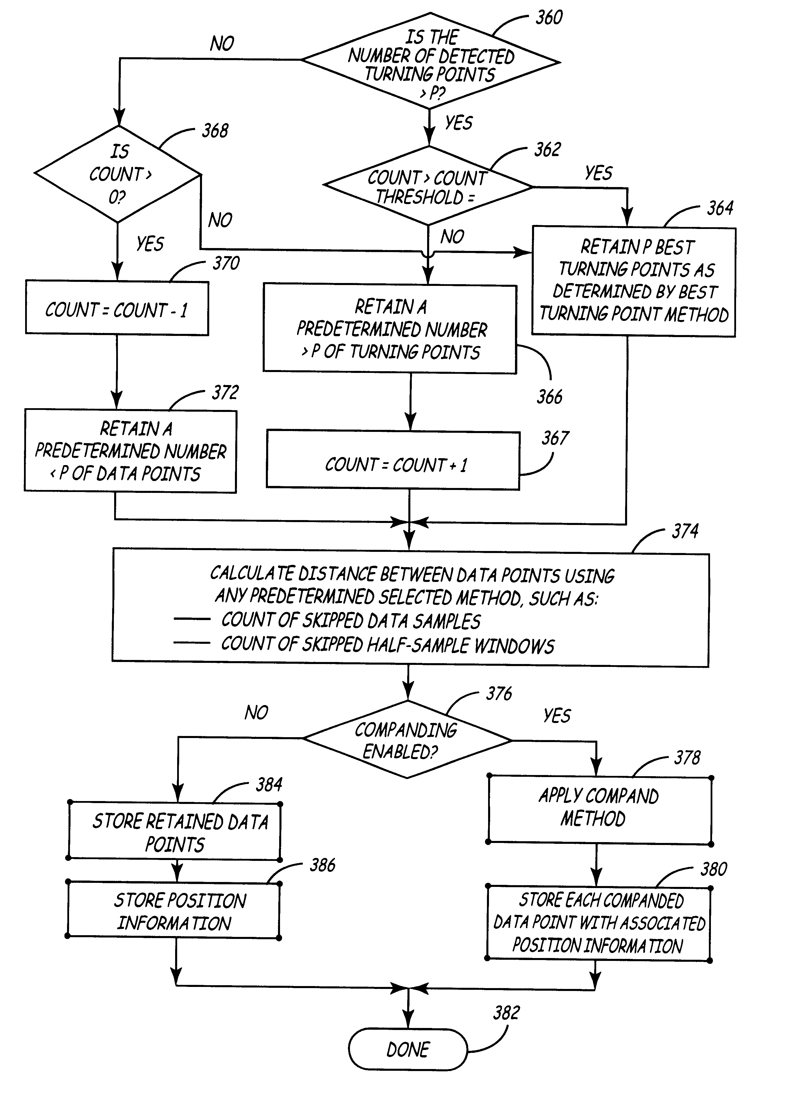
In some embodiments, the compression ratio may be variable. This allows a variable number of data samples within a given sample window to be retained depending on the number of turning points detected within the window. For example, if the frequency of the input signal is high such that a relatively large number of the data samples within the sample window are turning points, a larger-than-average number of data samples may be retained for that sample window. A smaller-than-average number of data samples may be stored during another sample window. This may occur, for example, in a window in which no turning points are detected. Since it is desirable to have the average number of samples retained per sample window approach some predetermined target average value, a count of the number of "excess" data points that have been retained as compared to the target average is maintained. When this excess count exceeds a predetermined threshold value, the number of data points that may be retained during subsequent sample windows is temporarily reduced until the average number of saved data points per frame once again approximates the predetermined target average.

Problems solved by technology

Monitoring systems often have storage limitations.
Cost, size, power consumption, and the sheer volume of data over time have limited external real-time Holter monitors to recording, at most, only twenty-four hour data segments.
Storage constraints are even more severe in implantable EGM monitoring systems, wherein conserving both power and space are prime considerations.
At this rate, the storage requirements for even short EGM segments become prohibitive in IMDs given the inherent space and power constraints.
Moreover, it would take up to five hours to transfer a twenty-four hour data segment employing current telemetry transmission techniques.
In these cases, the reduction in sampling rate results in loss of data.
This may result in the loss of the slope and shape of the original waveform, making it difficult or impossible for the medical care providers to use the information to make a correct diagnosis.
Loss-less compression modes are computationally expensive, resulting in a more complex circuit design, increased power consumption, and a longer data processing time.
These techniques may also require a considerable amount of memory to perform.
As a result, the amount of memory needed to store the compressed data cannot be determined in advance.
Lossy techniques require less processing power to implement.
However, when data is compressed using a lossy method, some information is lost when the compressed data is used to re-construct the original waveform.
In general, this is not acceptable, however, because many types of cardiac signals including Ventricular Tachycardia (VT), Ventricular Fibrillation (VF), Sinus Tachycardia (ST), and Atrial Fibrillation(AF) include virtually no baseline segments.
The AZTEC algorithm has been used to store ECG data for automatic analysis functions such as QRS detection, but it has proven to be generally inadequate for a visual presentation of the data.
This method uses a straight line approximation of the waveform to store the ECG data, and does not generally permit substantial data compression.
Therefore, the allowable error in the P-wave and T-wave regions limit the overall compression.
256-259, T. J. Lynch. However, this technique is not considered adaptable for use in IMDs because of the processing power required to compress and store the data points in real time.
These techniques are relatively computationally intensive and are batch oriented.
This means that these methods operate on a block of sequential data points at one time, and therefore are not easily implemented in integrated circuit hardware.

Method used


Image

  • Method and apparatus for data compression of heart signals
  • Method and apparatus for data compression of heart signals
  • Method and apparatus for data compression of heart signals

Examples


first embodiment

If it is determined that both X.sub.1 and X.sub.2 are turning points, the current invention provides superior data compression by retaining the "best" turning point. The best turning point may be selected using one of several embodiments of Applicants' invention. the "unshared" legs of the portion of the waveform in question are used to determine the best turning point. This is best illustrated by considering FIG. 4.

FIG. 4 is a timing diagram of a QRS complex as may appear in an EGM signal, and illustrates application of the "largest unshared leg" embodiment of the best turning point system. In this example, data points 220, 222, 224, and 226 will be considered X.sub.0, X.sub.1, X.sub.2, and X.sub.3, respectively. According to this embodiment, a comparison is made between the waveform segment between X.sub.0 and X.sub.1, and the waveform segment between X.sub.2 and X.sub.3. More specifically, the difference between the waveform amplitude (which in this instance is a voltage measure...

case i

{[(V.sub.1 -V.sub.0)(V.sub.2 -VI.sub.1)0)]} (CASE I)

OR

case ii

{[V.sub.1 -

then retain X.sub.1, otherwise, retain X.sub.2.

Case I selects X.sub.1 when X.sub.1 is the only turning point. Case II selects X.sub.1 when both X.sub.1 and X.sub.2 are turning points and X.sub.2 is less than X.sub.1. In this case, the best turning point is therefore the turning point that is the least positive. When applied to sample points X.sub.1 and X.sub.2 of FIG. 3, this mechanism will retain X.sub.1 since V.sub.1 is less positive than V.sub.2.

Cascading

As mentioned previously, the improved turning point mechanism may be applied multiple times to the same data set in a cascaded fashion to achieve a higher compression ratio. For example, applying the improved turning point process to a data set once will achieve two-to-one data compression. The method may be applied to the compressed data set yet again to achieve four-to-one compression. Applying the method ye...


PUM


Abstract

An improved turning point system and method for performing data compression is disclosed. The system improves the conventional turning point compression method by selecting a predetermined number of the "best" turning points in the sample window including data samples X0 and XN. From this sample-window, ones of the data samples X1 through X(N-1) will be identified as turning points using a selected one of a disclosed set of turning point detection methods. In one embodiment, a turning point is identified by determining that the slopes in the lines interconnecting adjacent data points have different polarities. In an alternative embodiment, a data sample XM is considered a turning point if the slope of the line between the data samples XM and X(M+1) has a different polarity as compared to the slope of the last waveform segment that was encountered that did not have a slope of zero. According to one mechanism, amplitude thresholding is used to detect whether an identified turning point is likely the result of noise such that the turning point status of the data sample should be disregarded. After data samples are identified as turning points, ones of the identified turning points are identified as the "best" turning points to be selected for retention. The best turning points may be identified by determining which waveform segment included within a sample window has the largest change of amplitude. An alternative embodiment detects which of the turning points has the greatest signal amplitude compared to a reference value. Yet another embodiment selects as the best turning point that point having an amplitude that differs the most from the amplitude of the first data sample in the sample window. Still other embodiments retain the turning point having an amplitude which is more positive, or alternatively, more negative, than the other data samples. According to one aspect of the invention, the compression ratio varies based on the frequency of the input waveform. In another embodiment, position data is retained to indicate the relative position of retained data samples as compared to the position of other retained data samples. This position data may be calculated at a frequency that is less than the frequency of the sampled data.

Description

The present invention relates to data compression of sampled physiological signals such as electrocardiogram signals; and, more particularly, to methods and apparatus for performing the data compression employing improved turning point methods.ElectroCardioGram (ECG) monitoring systems such as Holter monitors are available to be worn externally by a patient to record electrical signals produced by the heart. Other ElectroGraM (EGM) monitors may be implanted within the body of a patient to record similar cardiac signals. Such monitoring systems are described in U.S. Pat. No. 5,312,446 and in U.S. Pat. No. 4,947,858, both of which are assigned to the assignee of the current invention, and are incorporated herein by reference.Monitoring systems often have storage limitations. Cost, size, power consumption, and the sheer volume of data over time have limited external real-time Holter monitors to recording, at most, only twenty-four hour data segments. As an alternative, multiple shorter...

Claims


Application Information

Patent Timeline
Patent Type & Authority Patents(United States)
IPC IPC(8): A61B5/00A61B5/0452A61N1/372
CPCA61B5/0006A61B5/0031A61B5/0452A61B5/04525A61B5/7232A61B5/7203A61B5/35A61B5/349
Inventor SPLETT, VINCENT E.LEE, BRIAN B.COMBS, WILLIAM J.
Owner MEDTRONIC INC
Why Eureka
Try Eureka