Acoustic resonance phase locked photoacoustic spectrometer

a phase locked, photoacoustic spectrometer technology, applied in the direction of instruments, color/spectral property measurements, optical radiation measurements, etc., can solve the problems of inapplicability to the vast majority of people, inconvenient teaching, and inconvenient us

Inactive Publication Date: 2003-08-19
SOUTHWEST SCI
View PDF8 Cites 49 Cited by
  • Summary
  • Abstract
  • Description
  • Claims
  • Application Information

AI Technical Summary

Benefits of technology

A primary advantage of the present invention is that it can operate at high frequencies and can be used in measurement of flowing gaseous species.
Other objects, advantages and novel features, and further scope of applicability of the present invention will be set forth in part in the detailed description to follow, taken in conjunction with the accompanying drawings, and in part will become apparent to those skilled in the art upon examination of the following, or may be learned by practice of the invention. The objects and advantages of the invention may be realized and attained by means of the instrumentalities and combinations particularly pointed out in the appended claims.
The accompanying drawings, which are incorporated into and form a part of the specification, illustrate several embodiments of the present invention and, together with the description, serve to explain the principles of the invention. The drawings are only for the purpose of illustrating a preferred embodiment of the invention and are not to be construed as limiting the invention. In the drawings:
FIG. 1 is a schematic diagr...

Problems solved by technology

Absorption by the target species of incident optical energy results in a transient heating of the gas.
Unfortunately, resonance frequencies depend on the local speed of sound which can change with temperature and gas composition.
Several disadvantages of this approach are apparent.
If the cell geometry changes differently for the two frequencies (due, for example, to a mechanical stress), the fr...

Method used


Image

  • Acoustic resonance phase locked photoacoustic spectrometer
  • Acoustic resonance phase locked photoacoustic spectrometer
  • Acoustic resonance phase locked photoacoustic spectrometer

Examples


example 1

Amplitude Modulation

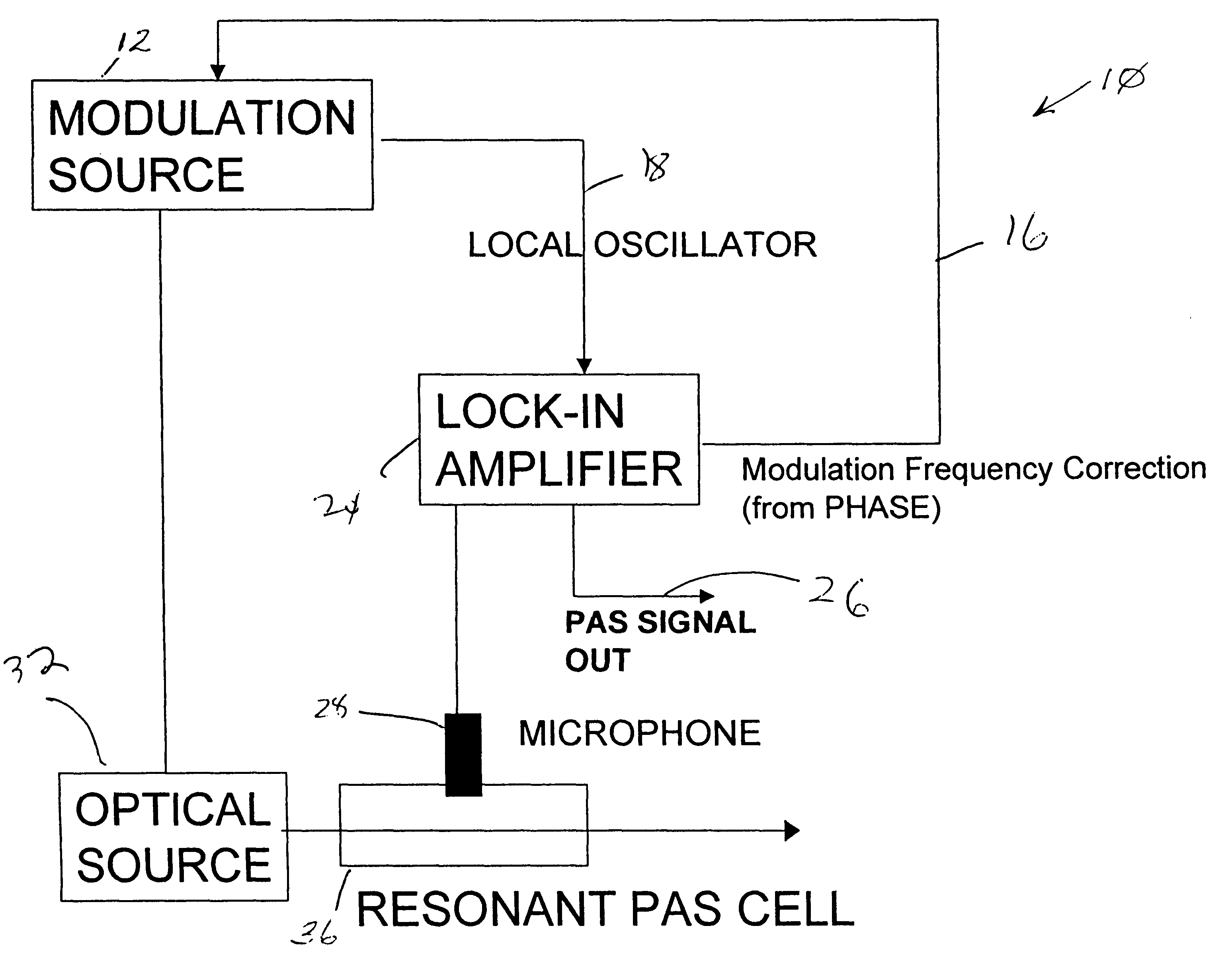
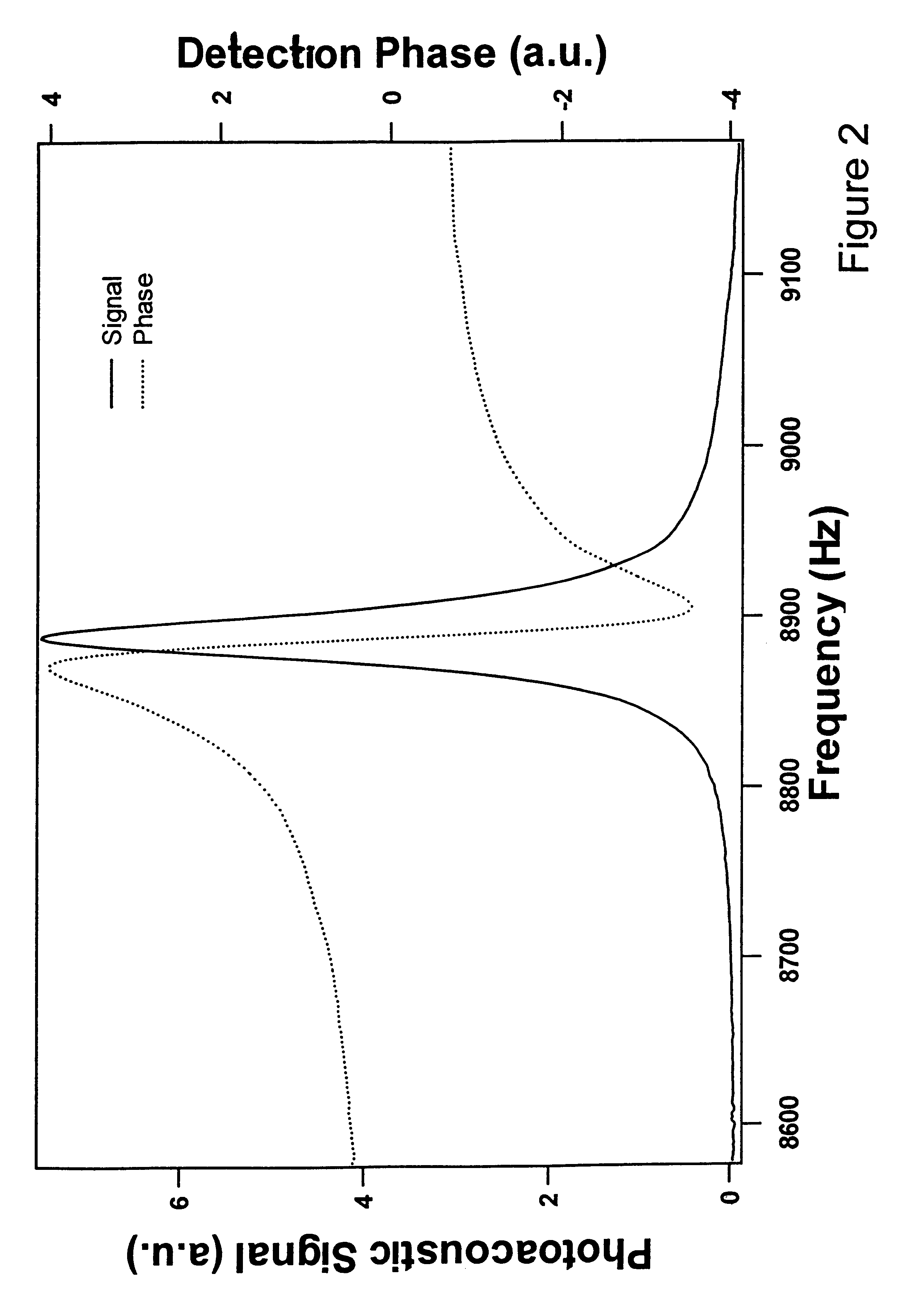
A 1380 nm broadband light emitting diode (LED) was used as the optical source. Amplitude modulation was achieved by 100% square wave modulating the injection current to the LED. Thus, the LED was turned on and off at the injection current modulation frequency. Using a nominal 2" inner diameter cylindrical cell, the first radial resonance was determined to be around 8800 Hz. The acoustic signal was generated by moisture absorption in this wavelength region. The detection phase of the acoustic carrier frequency was used to lock the modulation frequency to the center of the cell acoustic resonance as the moisture content of the air was raised.

example 2

Wavelength Modulation

A 1392.5 nm single mode distributed feed back (DFB) diode laser was used as the optical source. The laser was utilized to detect moisture. Wavelength modulation was implemented by modulating the laser injection current. DFB lasers scan nearly linearly in wavelength with injection current. Modulation was at one half the first radial resonance frequency, around 4400 Hz, and detected at 2 f or 8800 Hz. When the laser was on the line center of the moisture absorption sound was produced at 2 f which was enhanced by the acoustic cell resonance. Acoustic resonance locking was implemented using the present detection phase method. Also, wavelength modulation of the DFB laser was achieved directly at 8800 Hz and detected at 1 f.


PUM


Abstract

A photoacoustic spectroscopy method and apparatus for maintaining an acoustic source frequency on a sample cell resonance frequency comprising: providing an acoustic source to the sample cell to generate a photoacoustic signal, the acoustic source having a source frequency; continuously measuring detection phase of the photoacoustic signal with respect to source frequency or a harmonic thereof; and employing the measured detection phase to provide magnitude and direction for correcting the source frequency to the resonance frequency.

Description

1. Field of the Invention (Technical Field)The present invention relates to high-sensitivity detection of contaminants in gases by optical techniques generally termed photoacoustic spectroscopy (PAS) or optoacoustic spectroscopy.2. Background ArtNote that the following discussion refers to a number of publications by author(s) and year of publication, and that due to recent publication dates certain publications are not to be considered as prior art vis-a-vis the present invention. Discussion of such publications herein is given for more complete background and is not to be construed as an admission that such publications are prior art for patentability determination purposes.Photoacoustic spectroscopy is a known technique for high sensitivity detection of trace gases. Absorption by the target species of incident optical energy results in a transient heating of the gas. If the incident optical energy is modulated then the gas is periodically heated which creates a time-varying press...

Claims


Application Information

Patent Timeline
IPC IPC(8): G01N21/17G01N21/27
CPCG01N21/1702G01N21/274G01N2021/1704
Inventor PILGRIM, JEFFREY S.BOMSE, DAVID S.SILVER, JOEL A.
Owner SOUTHWEST SCI
Why Eureka
Try Eureka