
Yarn processing device and use thereof

a processing device and yarn technology, applied in the field of yarn processing devices, can solve problems such as yarn processing spinnerets

Inactive Publication Date: 2003-08-26
OERLIKON HEBERLEIN TEMCO WATTWI
View PDF10 Cites 6 Cited by
  • Summary
  • Abstract
  • Description
  • Claims
  • Application Information

AI Technical Summary

Benefits of technology

The invention is based on the task to develop yarn processing spinnerets and / or yarn processing elements which have a maximum of wear-resistance as regards the preparation and which facilitate a long service life. A special portion of the task was to create a spinneret connection for separated yarn processing element which facilitates a swift and precise positioning and can be used for highly wear-resistant materials such as ceramics including for thermal treatments.
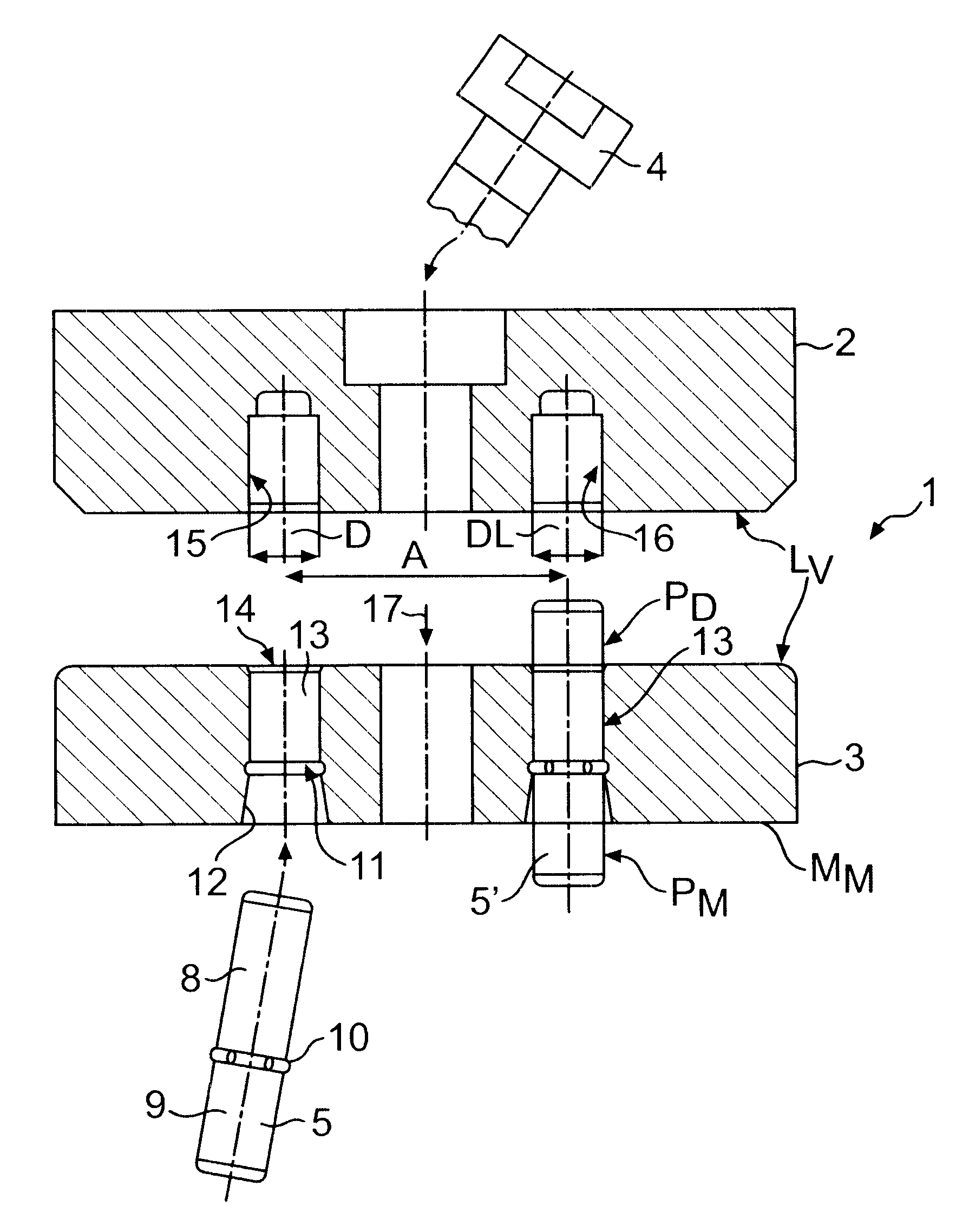
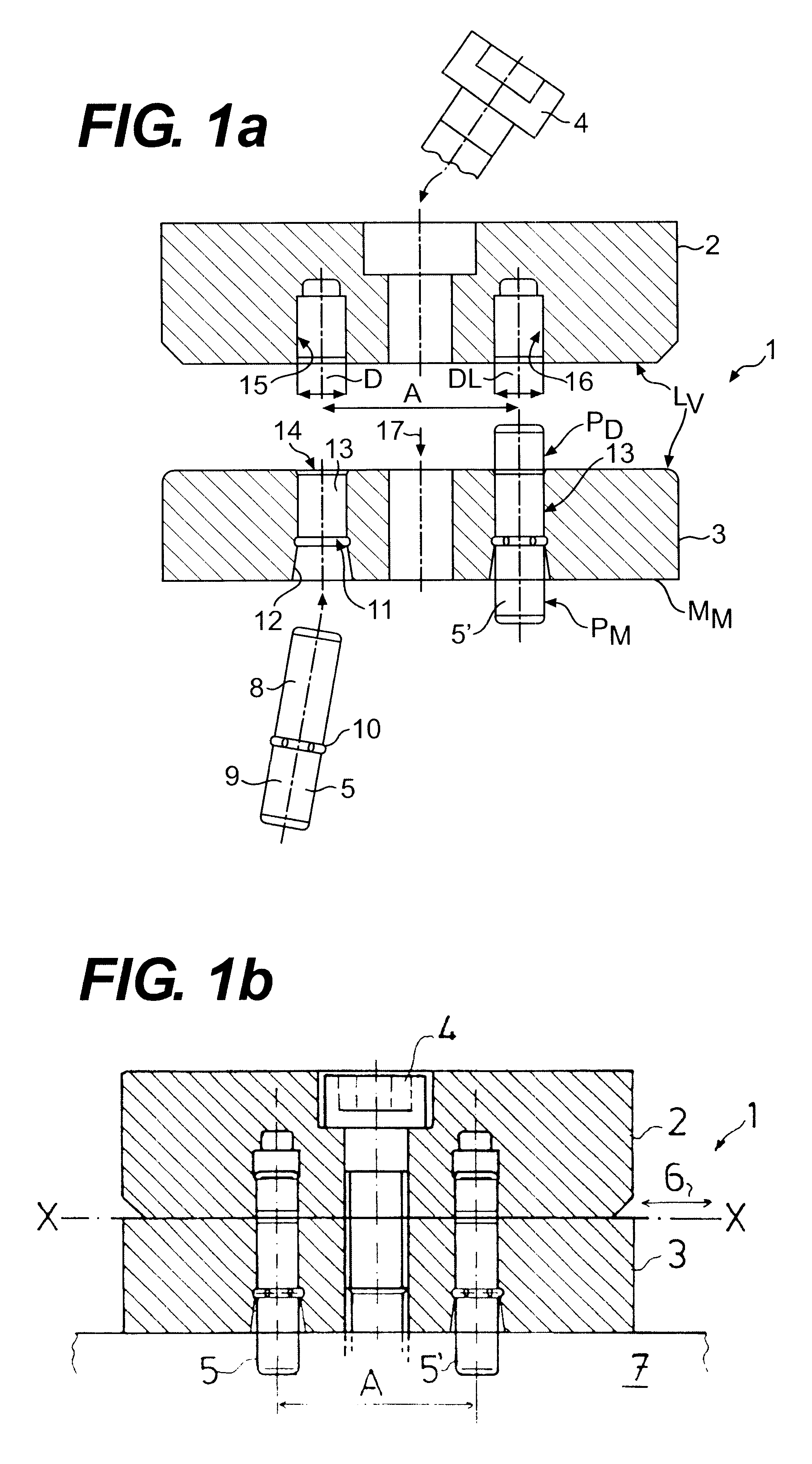
The inventors have discovered that a spinneret with a connection device remains safe to operate only if the spinneret can resist to pressure, heat, steam, or chemical substances. The hitherto known adhesive connections did not represent a satisfactory solution to all problems encountered in practical operations. What is more, a study of an adhesive connection can only be made insofar as practical conditions are actually known at present. However, the composition of an adhesive connection cannot be determined with a view to the exposure to chemical substances unknown today but possibly employed in the future. At best, a statement can be made with respect to exposure to an increased heat or moisture. Preferably, with the new solution, the connection devices are arranged in a common orientation, preferably aligned with the yarn run. Surprisingly it was established that with a corresponding pin connection--as compared with the state of the art--it is possible to substantially reduce the size of the entire spinneret element and have them built quasi in a miniaturized form. Specifically if a dual spinneret is used or if several spinnerets are arranged in parallel, the separation between two adjacent yarn runs can be essentially smaller than before; in some applications this even had repercussions on the size of the galette. Owing to the new connection, the possible miniaturization allows the implementation of additional yarn runs for each individual machine size, and, correspondingly, an increase of the overall performance of the machine. This means that the connection device as an assembly / disassembly aid--otherwise rather known from the watch and clock engineering--and the line-shaped application offers unexpected advantages. The frictional connection of the elements can be ensured--just as with the state of the art--by means of a classical screw connection. Specifically when used as an interlacing spinneret and as a thermal treatment element and also--this will yet be shown--as a migration spinneret, the new solution is very advantageous.
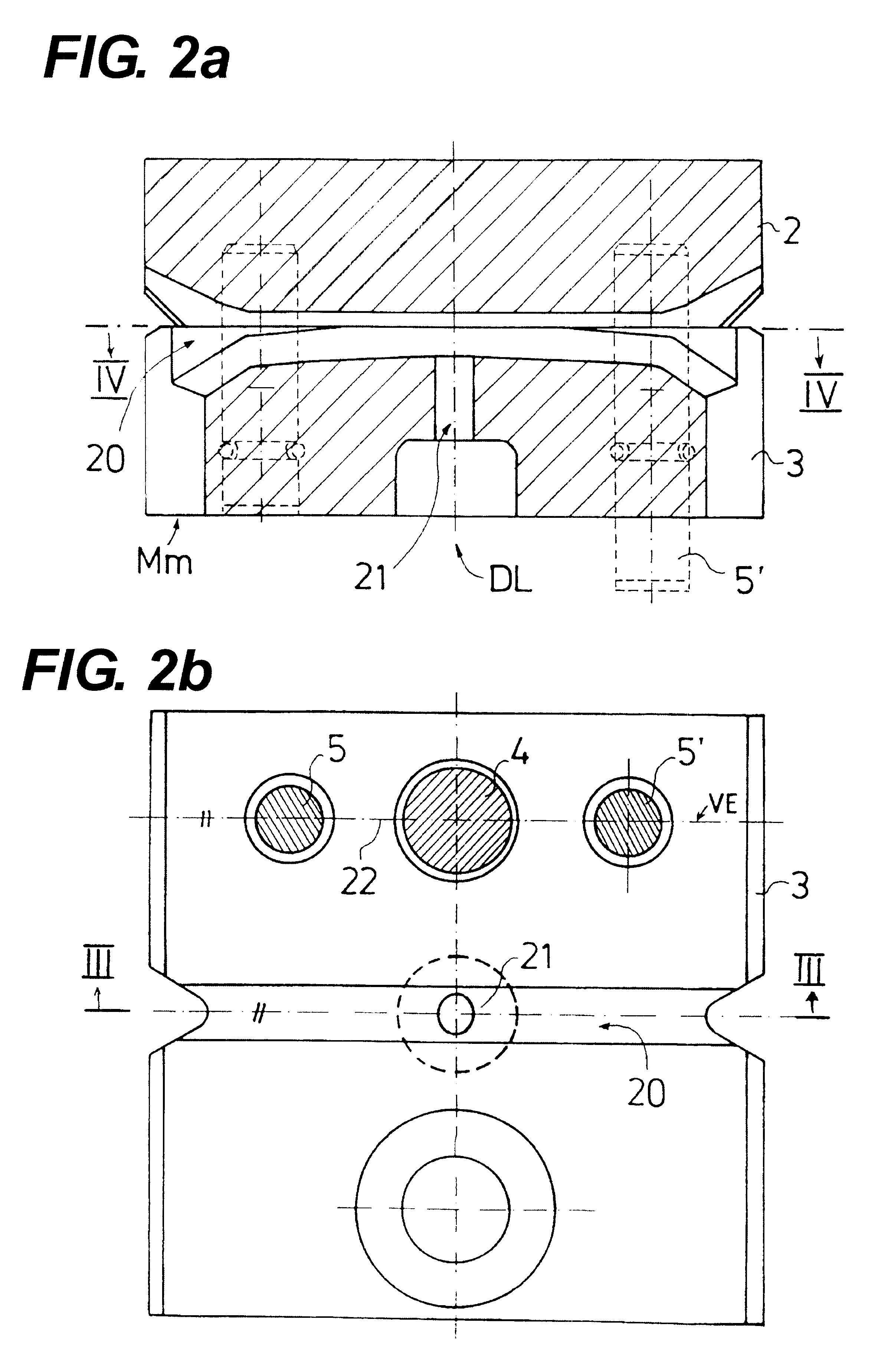
FIGS. 2a and 2b illustrate a specific form of a yarn canal 20 for the swirl of yarn using pressurized air or another medium. DL marks the spot envisaged for the pressurized air connection whereby the pressurized air will be introduced into the yarn canal 20 via a pressurized air inlet bore 21 at a pressure between e.g. 1 and 6 bar. It is preferred that both dowel pins 5, 5' are arranged on a common straight line (VE) together with bolt 4. This renders both an optimal dowel connection and frictional connection, and it facilitates a narrow separation for the yarn run (as is illustrated in FIG. 5b).

Problems solved by technology

The improvement of quality by means of superheated steam, e.g. the relaxation during the stretch process or after another preceding procedural intervention is a very demanding process.
In all cases, the spinneret elements are produced from a highly wear-resistant material, because their service life would otherwise be too short.
The main source of problems for the yarn processing spinnerets lies in the preparation.
The interaction of pressure, heat, moisture, and a variety of chemical substances during the preparation causes very aggressive conditions for the material of the yarn processing spinnerets, above all, however, for any connection means utilized on the spinnerets.

Method used


Image

  • Yarn processing device and use thereof
  • Yarn processing device and use thereof
  • Yarn processing device and use thereof

Examples


Embodiment Construction

The invention is based on the task to develop yarn processing spinnerets and / or yarn processing elements which have a maximum of wear-resistance as regards the preparation and which facilitate a long service life. A special portion of the task was to create a spinneret connection for separated yarn processing element which facilitates a swift and precise positioning and can be used for highly wear-resistant materials such as ceramics including for thermal treatments.

The solution proposed in accordance with the invention is characterized in that the connection of the separated spinnerets presents at least one dowel pin which is contained in at least one part of the element by means of mechanical clamping devices or holding devices and lead in a second part through a corresponding bore for the purpose of positioning and assembly / disassembly of the dowel pin connection in axial direction.

The inventors have discovered that a spinneret with a connection device remains safe to operate onl...


PUM

PropertyMeasurementUnit
pressureaaaaaaaaaa
pressureaaaaaaaaaa
pressureaaaaaaaaaa

Abstract

The invention relates to a pin assembly which keeps single-piece, two-piece or multi-pieced yarn processing elements, especially yarn interlacing spinnerets or thermal treatment elements, in an exact position during an entire service life, despite the extreme effects of preparations used. Instead of a traditional soldered joint or an adhesive connection, mechanical clamping means are used to fix the dowel pins to one part of the spinneret. Fixation of the dowel pins is not affected by heat or chemical preparations. The clamping means consists of a simple clamping ring holding the dowel pin in position directly inside the body of the spinneret between the clamping pin and an after-body. The novel positioning solution can be used with individual parts of spinnerets, parts of spinnerets in machines or multiple parts of spinnerets. The dowel pins enable the entire spinneret to be substantially miniaturized and allow narrow separation between various yarn runs, which was previously impossible. The invention can be used advantageously in interlacing spinnerets or in stream treatment elements.

Description

The invention relates to a yarn processing device fitted with a preferably separable screw connection of two processing elements made of highly wear-resistant material, especially ceramics, and the use thereof.STATE OF THE ARTThe processing of filament yarn has to achieve essentially two tasks. On the one hand the yarn made of industrially produced filaments is to be given a textile character and textile engineering properties. On the other, the yarn is processed with a view to specific quality features required for further processing and / or for the final product in some cases yarn qualities will be required which are not necessary with products made of natural fibers and--what is more--these cannot even be realized. The fields of application are within the industrial processing of textiles e.g. for the construction sector, automotive production but also for the manufacture of carpets and for specific textile products the sports and leisure industry offers. Moreover, spun yarn is to...

Claims


Application Information

Patent Timeline
Patent Type & Authority Patents(United States)
IPC IPC(8): D02G1/16D02J1/00D02J13/00D02J1/08
CPCD02G1/162D02J13/00
Inventor RITTER, HELMUTBUCHMULLER, PATRICKBERTSCH, GOTTHILFSCHWARZ, ERWIN
Owner OERLIKON HEBERLEIN TEMCO WATTWI
Learn More