Color separation prisms having solid-state imagers mounted thereon and camera employing same

Inactive Publication Date: 2003-09-02
FOVEON
View PDF26 Cites 24 Cited by
  • Summary
  • Abstract
  • Description
  • Claims
  • Application Information

AI Technical Summary

Benefits of technology

The method of the present invention is simpler than the prior-art methods, eliminates undesired reflections from glass surfaces between the prism and the surface of the imaging arrays, and eliminates the cost of a separate package for each imaging array. The method involves using an index-matched adhesive to adhere the imaging array directly to the prism face, thereby eliminating any air gap between the prism face and the surface of the imaging array. An essential aspect of the invention is to fabricate the prism in such a way that the effective optical path length from the input face to the three output faces is well matched. The index of refraction of optical glass changes with wavelength. If the color-separ

Problems solved by technology

Disadvantages of the sequential method are the cost and complexity of the mechanism used to sequentially place the color filters in the image path, that at least three times the exposure time is required, compared with that of a single sensor, that color artifacts are produced by moving objects in action images, and that synchronization with a flash lamp is problematic.
Disadvantages of the mosaic method are that three to four times the exposure time is required, compared with that of a single sensor, that color artifacts are produced due to details in the image aliasing against the periodic mosaic filter array, that the sensor is two to three times the area of a single-color s

Method used


Image

  • Color separation prisms having solid-state imagers mounted thereon and camera employing same
  • Color separation prisms having solid-state imagers mounted thereon and camera employing same
  • Color separation prisms having solid-state imagers mounted thereon and camera employing same

Examples


Embodiment Construction

Persons of ordinary skill in the art will realize that the following description of the present invention is illustrative only and not in any way limiting. Other embodiments of the invention will readily suggest themselves to such skilled persons having the benefit of this disclosure.

The present invention will work with many color-separation prism designs. Non-exhaustive examples include the prism assembly disclosed in U.S. Pat. No. 5,644,432, the prism assembly disclosed in U.S. Pat. No. 3,659,918, the prism assembly disclosed in U.S. Pat. No. 4,009,941, the prism assembly disclosed in U.S. Pat. No. 4,072,405, the prism assembly disclosed in U.S. Pat. No. 4,035,836, and the prism assembly disclosed in the article H. de Lang and B. Bouwhuis "Colour Separation in Colour-Television Cameras" Phillips Technical Review, vol. 24, no. 9, pp. 263-298, August 1963.

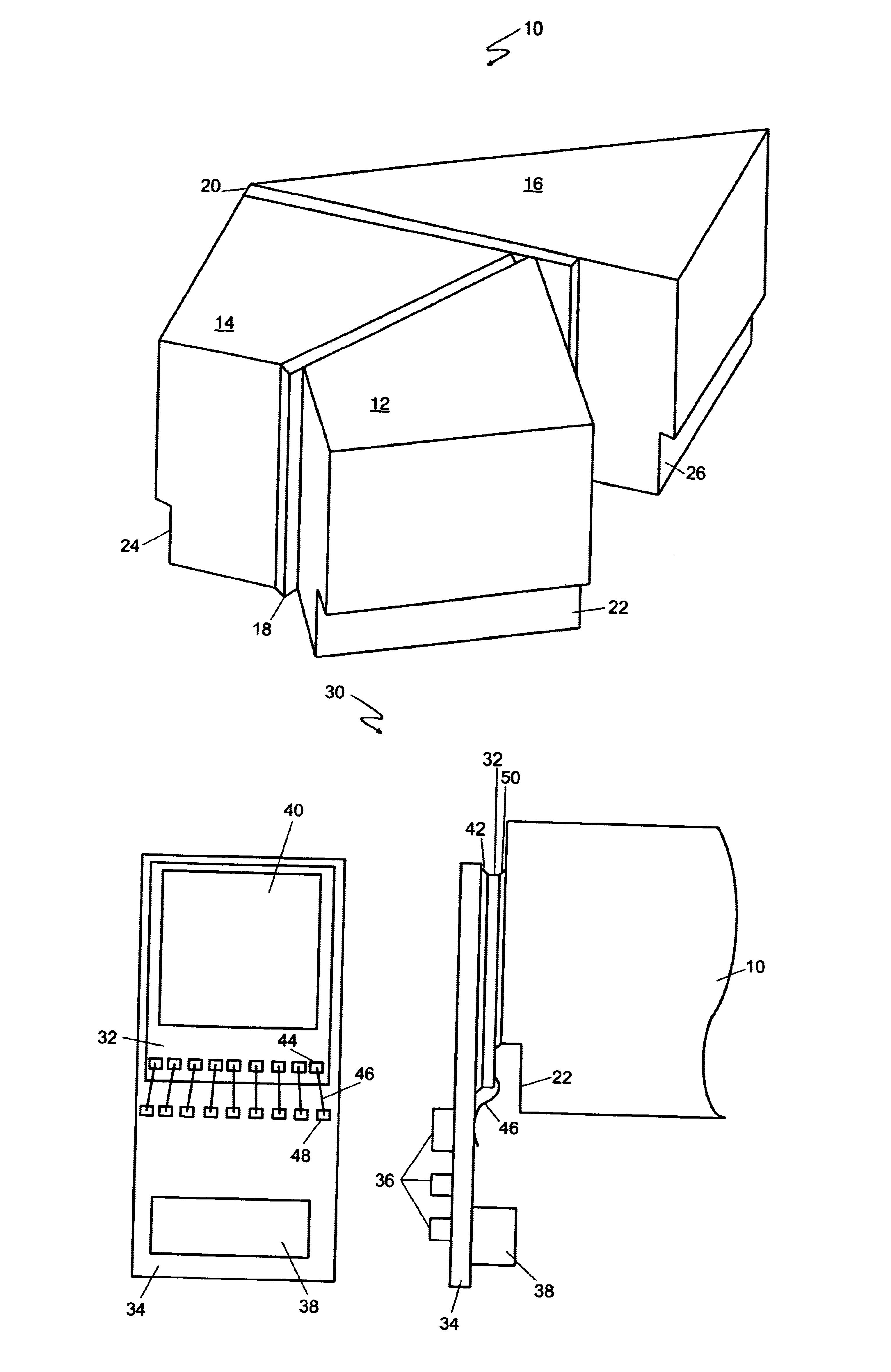
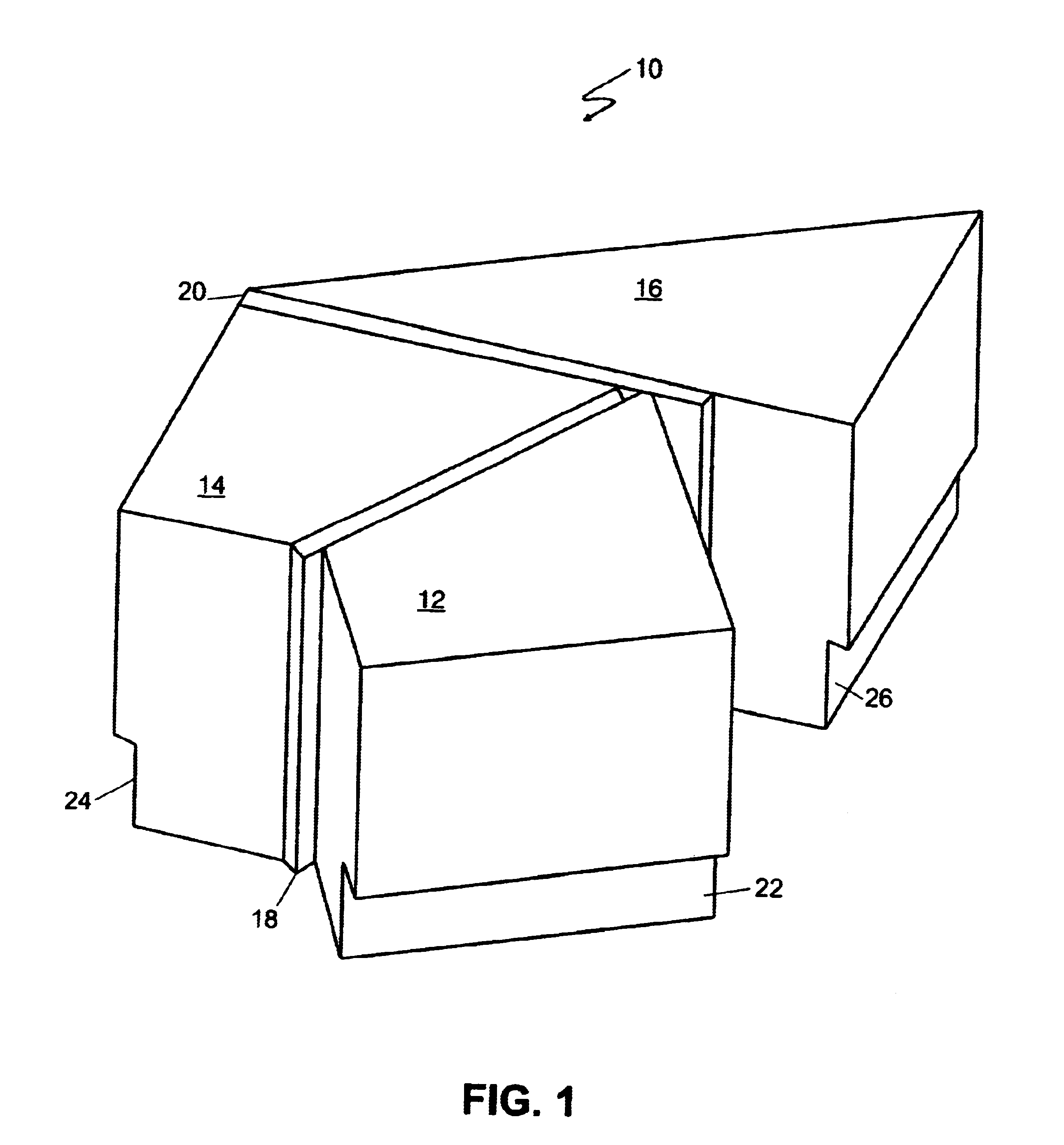
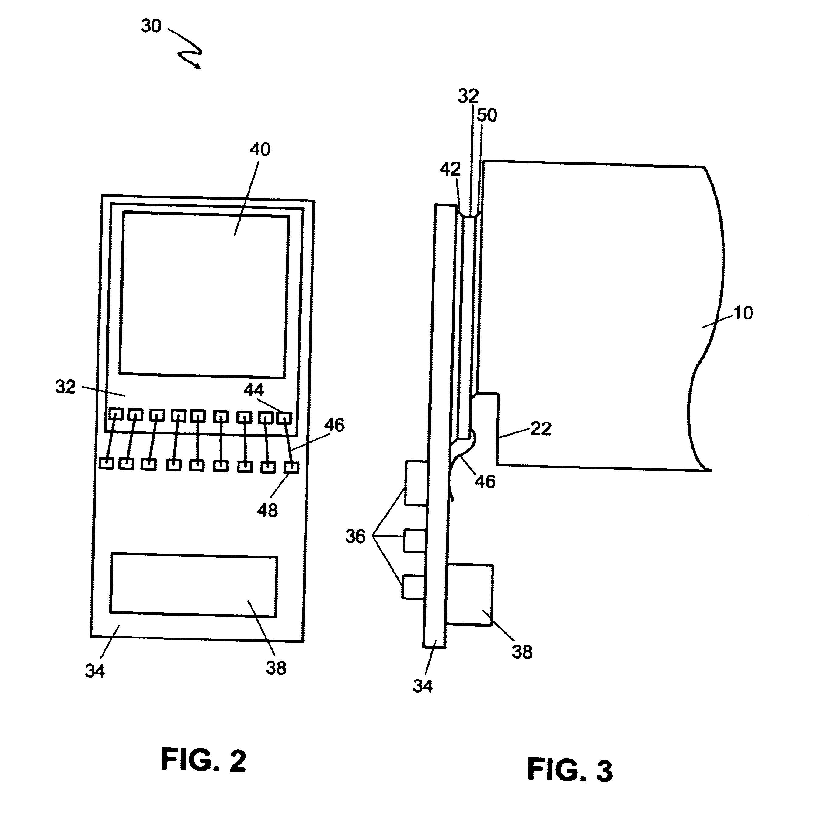
Referring first to FIG. 1, an isometric drawing of an illustrative color-separating prism 10 that may be used in the present inve...


PUM


Abstract

A method for attaching imagers to color-separation prisms includes the steps of: arranging three solid-state array image sensor integrated circuits behind and in close proximity to the output faces of a color-separating prism having substantially equal optical path lengths for the three paths, the three solid-state array image sensor integrated circuits each having a solid-state array image sensor and bonding pads for electrical connections disposed on a top face thereof; aligning the three sensors such that the images traversing the three paths are coincident within a pixel dimension of the image sensors; filling the space between each output face of the prism and the top face of the corresponding image sensor with index-matched adhesive; and causing the index-matched adhesive to become rigid while maintaining the alignment of the three image sensors.

Description

1. Field of the InventionThe present invention relates to solid-state imagers. More particularly, the present invention relates to solid state imagers mounted onto color separation prisms, methods for attaching such solid-state imagers to color separation prisms, and cameras employing same.2. The Prior ArtIn the art of electronic imaging, it is necessary to resolve the incoming image into a minimum of three primary colors. The principles are well understood, and are adequately described in the book "The Reproduction of Colour" by R. W. G. Hunt, published by Fountain Press, 1995. Historically, three principal methods have been employed, originally with photo-sensitive vacuum tube sensors (vidicons, image orthicons, etc.), and more recently with silicon CCD imaging chips.In the first method, the sensor is sequentially exposed to the image, first through a first filter, then through a second filter, then through a third filter. A separate image is captured through each filter, thus for...

Claims


Application Information

Patent Timeline
IPC IPC(8): G02B27/14H04N9/097H04N9/09H04N5/225
CPCG02B27/1013G02B27/1073G02B27/145H04N5/2253H04N9/097H04N23/54H04N23/16G02B27/10
Inventor MEAD, CARVER A.
Owner FOVEON
Why Eureka
Try Eureka