Apparatus and method for depositing a coating onto a surface of a prosthesis

a prosthesis and surface technology, applied in the field of implants, can solve the problems of obstructing the conduit, affecting the patient's comfort, and affecting the patient's comfort, and achieving the effect of reducing pain, reducing the risk of infection, and reducing the patient's comfor

Inactive Publication Date: 2003-09-09
ABBOTT CARDIOVASCULAR
View PDF31 Cites 315 Cited by
  • Summary
  • Abstract
  • Description
  • Claims
  • Application Information

AI Technical Summary

Problems solved by technology

A problem associated with the above procedure includes formation of intimal flaps or torn arterial linings which can collapse and occlude the conduit after the balloon is deflated.
To provide an efficacious concentration to the treated site, systemic administration of such medication often produces adverse or toxic side effects for the patient.
One disadvantage of dip-coating and spray-coating methods is the inability to control the exact geometrical pattern of coating on the stent or section of the stent.
Web-like defects are most prevalent in stents having tight patterns, for example coronary stents, such that the distance between the struts is very small.
Another disadvantage of both dip-coating and spray-coating stems from a low-viscosity requirement for the polymer solution in which the stent is dipped or with which the stent is sprayed.
A low viscosity solution can only be achieved by using a low molecular weight polymer or by using a very low concentration of polymer in the polymer solution.
Thus, both dip-coating and spray-coating methods have imposed limitations in type and concentration of applied polymers.
Like the dip-coating and spray-coating techniques, the sputtering and gas phase polymerization techniques do not allow control of the geometrical pattern of the coating and are quite limited in the selection of polymers that can be employed.
In addition, coating a stent with a polymer and a drug at the same time via sputtering or gas phase polymerization has not been demonstrated to be effective and risks degradation of the drug.
Moreover, techniques for applying a polymeric coating by sputtering or gas phase polymerization and later incorporating a drug into the applied polymeric coating are limited.

Method used


Image

  • Apparatus and method for depositing a coating onto a surface of a prosthesis
  • Apparatus and method for depositing a coating onto a surface of a prosthesis
  • Apparatus and method for depositing a coating onto a surface of a prosthesis

Examples


Embodiment Construction

Apparatus for Depositing a Composition onto a Prosthesis

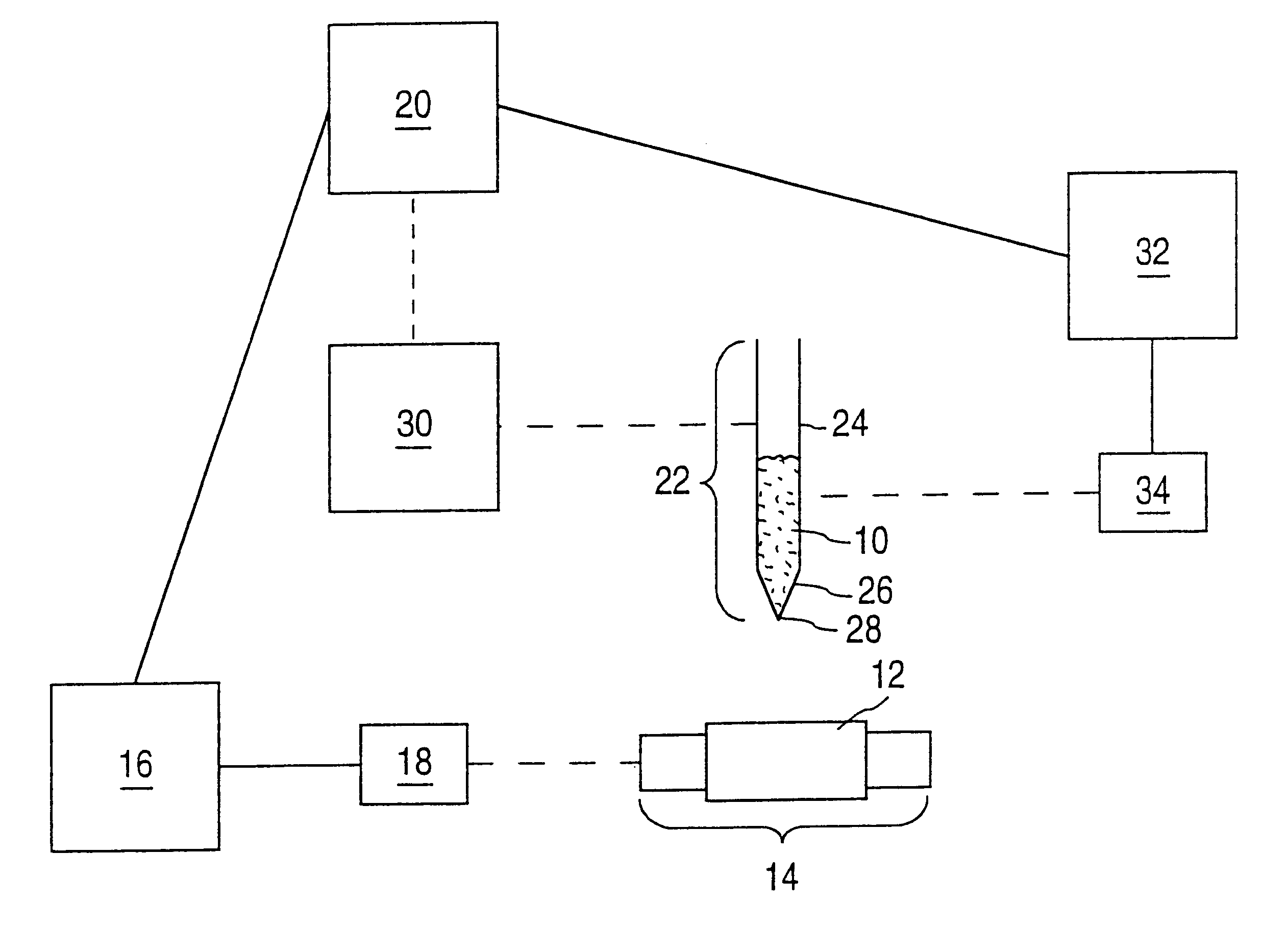
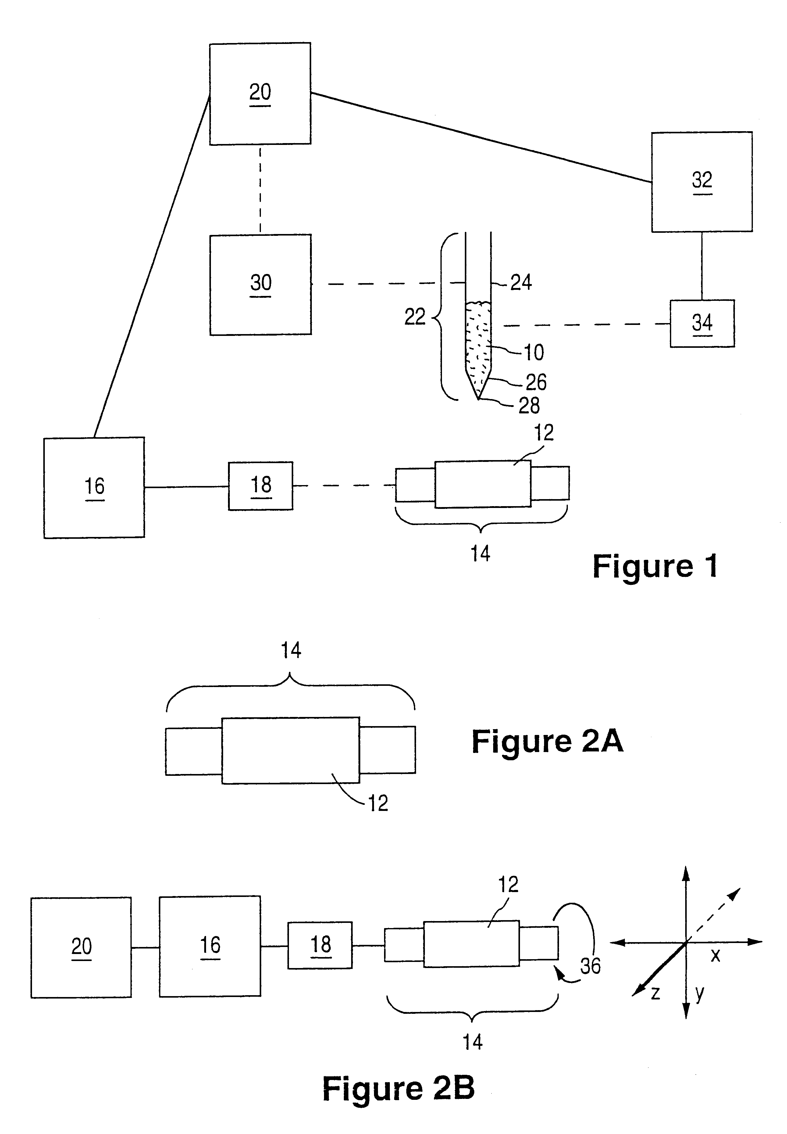
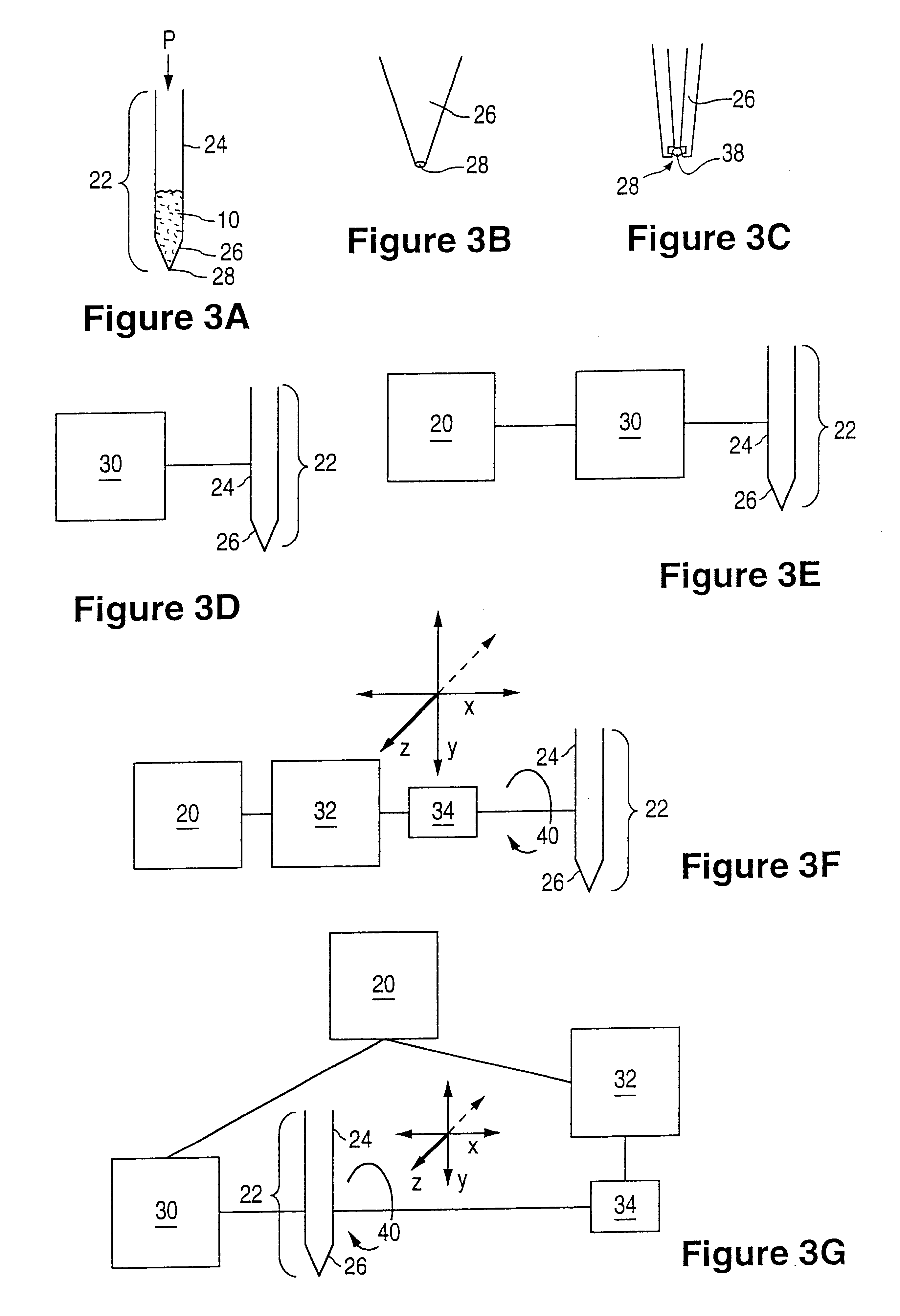
Referring now to the drawings, wherein similar parts are identified by like reference numerals, FIG. 1 illustrates the various components which may be involved in the deposition of a composition 10 onto a surface of a prosthesis 12 in accordance with an aspect of the present invention. A broken line between two components in FIG. 1 represents an optional coupling which is present in some, but not all, embodiments of the deposition method. Prosthesis 12 is supported in a holder assembly 14 which may be coupled to a holder motion control system 16 through a holder driving component 18. Holder motion control system 16 is in communication with CPU 20. A dispenser assembly 22 includes a reservoir 24 and a nozzle 26 having an orifice 28. Dispenser assembly 22 may be coupled to a delivery control system 30 which can be in communication with CPU 20. Dispenser assembly 22 may also be coupled to a dispenser motion control system 32 throu...


PUM

PropertyMeasurementUnit
angleaaaaaaaaaa
angle θ1aaaaaaaaaa
angle θ2aaaaaaaaaa

Abstract

A patterned coating on a prosthesis, for example a stent, and a method for forming the coating are disclosed. Additionally, an apparatus for forming the patterned coating is disclosed.

Description

1. Field of the InventionThis invention relates generally to implantable devices, such as an expandable intraluminal prosthesis, one example of which includes a stent. More particularly, the invention is directed to an apparatus and method for coating a prosthesis.2. Description of the Related ArtPercutaneous transluminal coronary angioplasty (PCTA) is a procedure for treating heart disease. A catheter assembly having a balloon portion is introduced percutaneously into the cardiovascular system of a patient via the brachial or femoral artery. The catheter assembly is advanced through the coronary vasculature until the balloon portion is positioned across the occlusive lesion. Once in position across the lesion, the balloon is inflated to a predetermined size to radially compress against the atherosclerotic plaque of the lesion to remodel the vessel wall. The balloon is deflated to a smaller profile to allow the catheter to be withdrawn from the patient's vasculature.A problem associ...

Claims


Application Information

Patent Timeline
Patent Type & Authority Patents(United States)
IPC IPC(8): A61L31/14A61L31/16A61L31/10A61L31/08B05D1/26A61F2/06A61F2/90
CPCA61L31/10A61L31/16B05D1/26A61F2/91A61L2300/606B05D1/002B05D1/40B05D3/107A61F2250/0068
Inventor CASTRO, DANIELWU, STEVENWOOLBRIGHT, KEVIN L.SCHEINPFLUG, KURT W.HOSSAINY, SYED F. A.CHEN, LI
Owner ABBOTT CARDIOVASCULAR
Why Eureka
Try Eureka