

Injection compression molding method for optically formed product
a technology of injection compression and optical molding, which is applied in the direction of optical articles, domestic applications, other domestic articles, etc., can solve the problems of deteriorating the optical properties of the lens, forming a quality problem, and impairing the appearance of the lens
- Summary
- Abstract
- Description
- Claims
- Application Information
AI Technical Summary
Benefits of technology
Problems solved by technology
Method used
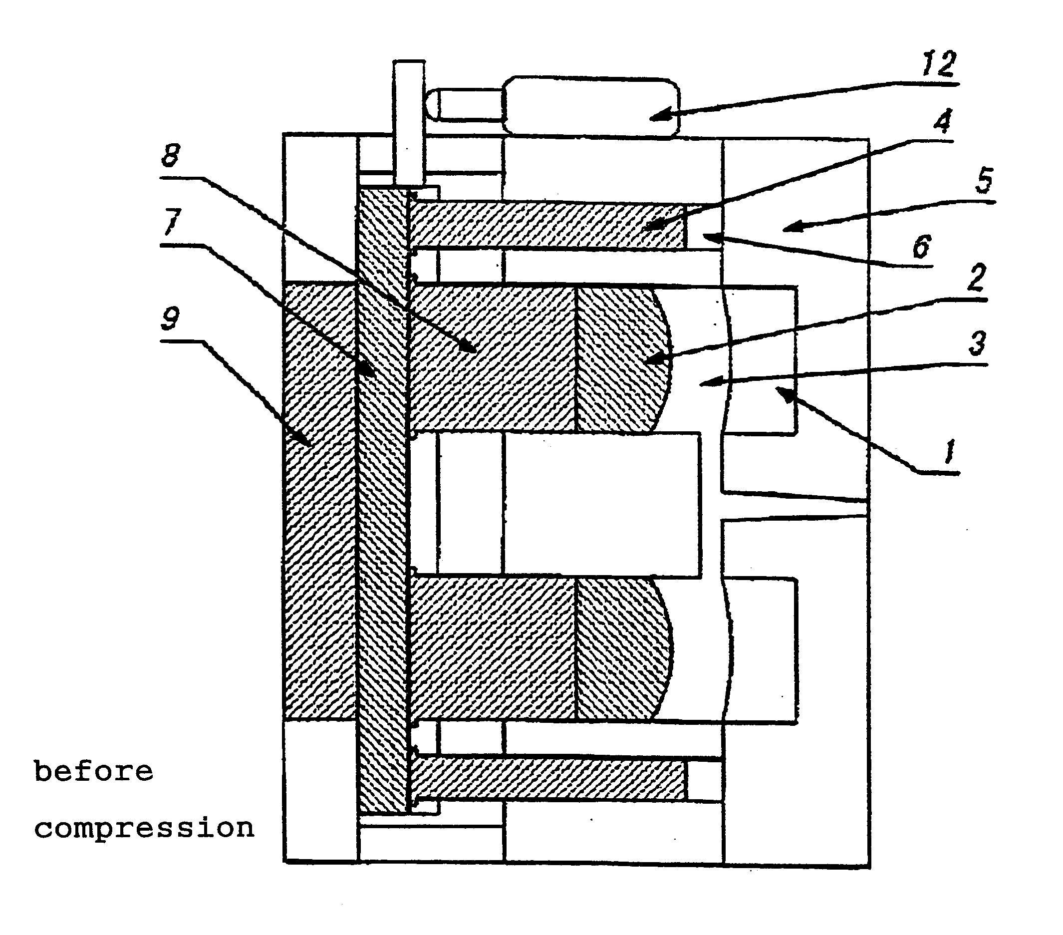
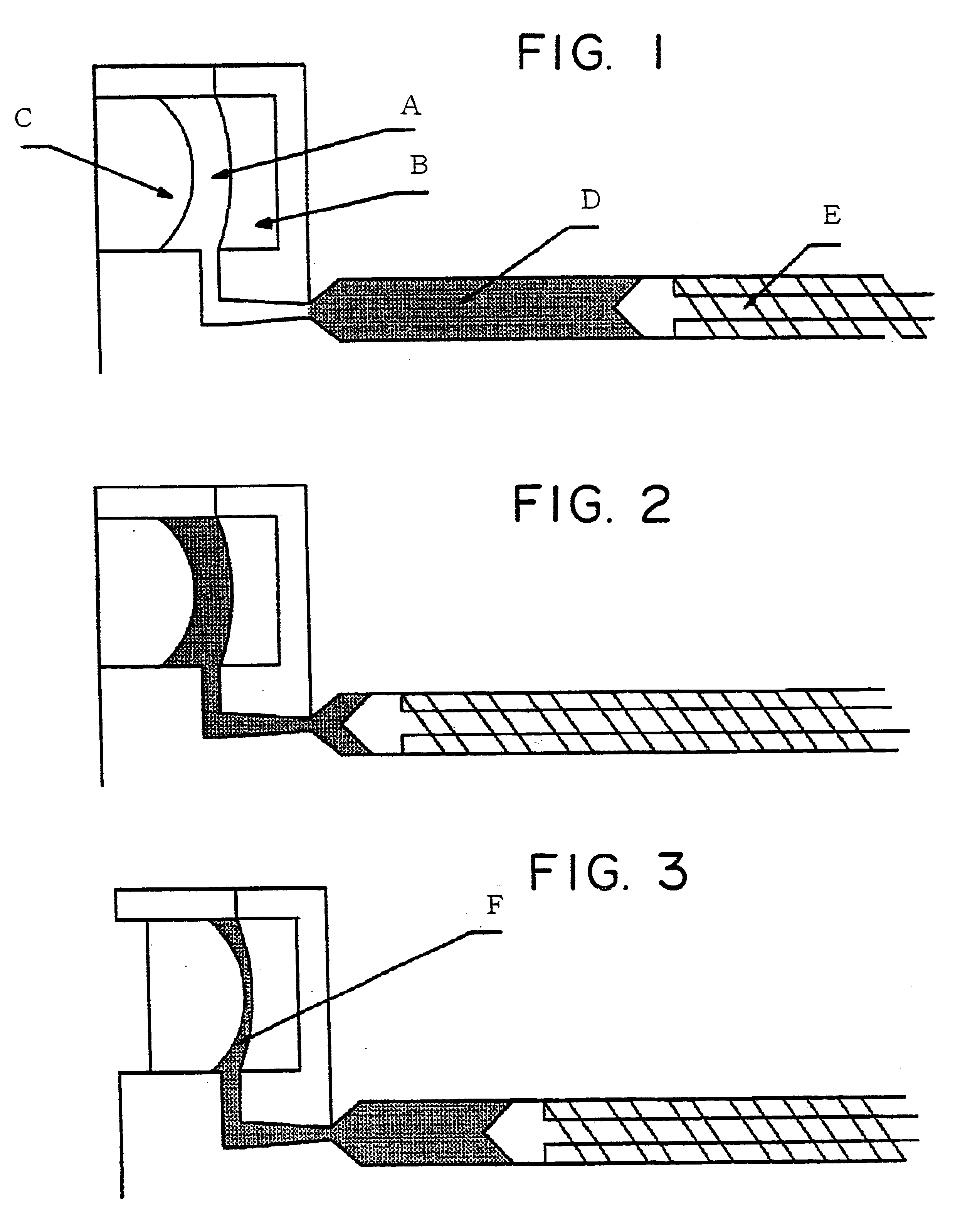
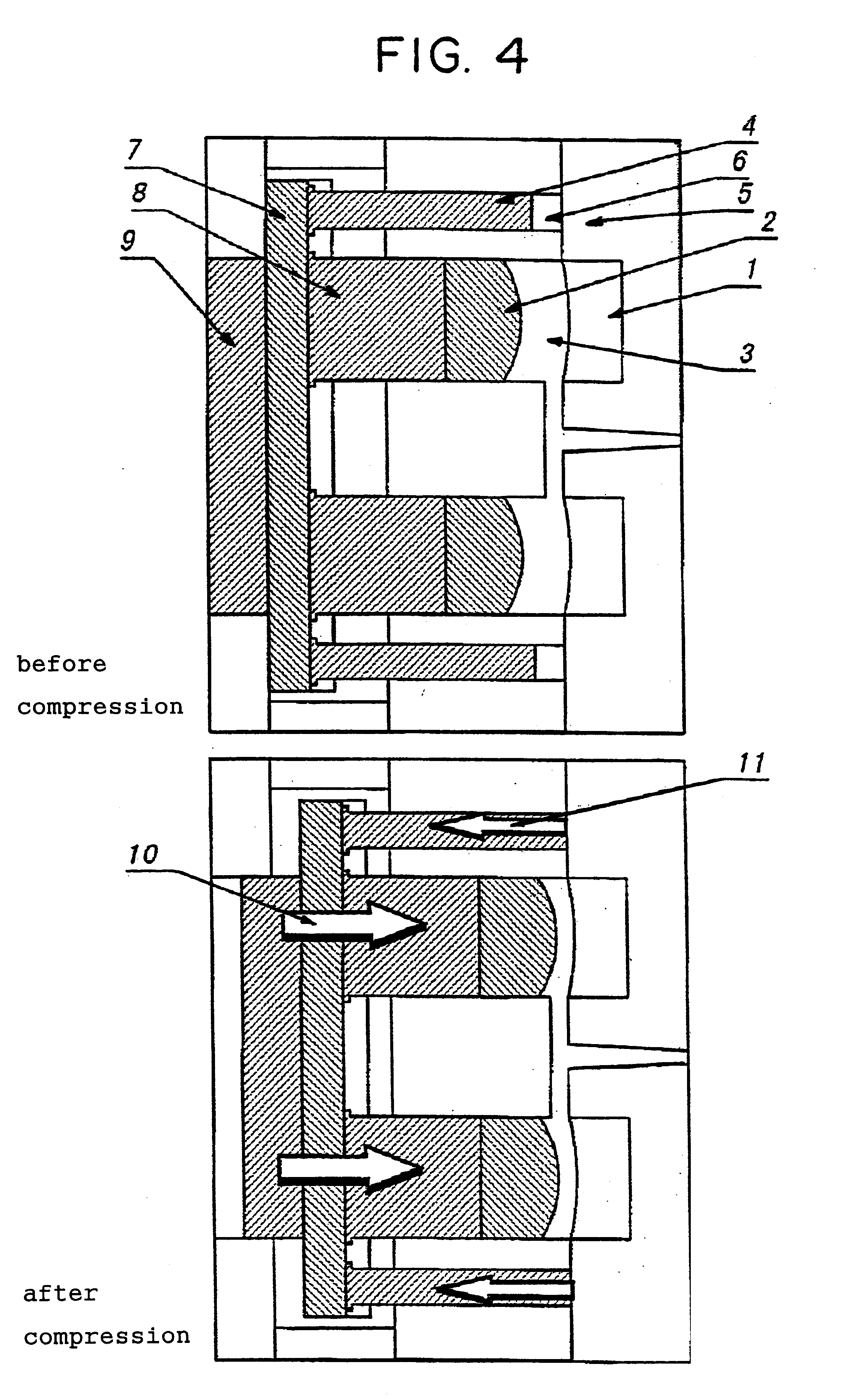
Image

Examples
example 1
0.3 part by weight of 2-(2'-hydroxy-5'-t-octyl)benzotriazole as an ultraviolet light absorber, 0.03 part by weight of tris(nonylphenyl)phosphite as a heat stabilizer and 0.2 part by weight of monoglyceride stearate as a releasing agent were blended with 100 parts by weight of a polycarbonate resin having a viscosity average molecular weight of 22,500 synthesized from bisphenol A and phosgene, and the obtained blend was formed into the following polycarbonate resin minus spectacle lens (concave lens) by injection compression molding using the injection molding machine (SYCAPSG220) of Sumitomo Heavy Industries, Ltd. and a core compression mold.
The main molding conditions at this point were as follows.
The movable lens mold was moved back, the cavity was expanded to a lens center thickness of 7.6 mm (expansion volume ratio of 215%) before injection, the resin was injected into the cavity, the movable lens mold was compressed when the resin pressure became 30 MPa until the compression co...
example 2
0.3 part by weight of 2-(2'-hydroxy-5'-t-octyl)benzotriazole as an ultraviolet light absorber, 0.03 part by weight of tris(nonylphenyl)phosphite as a heat stabilizer and 0.2 part by weight of monoglyceride stearate as a releasing agent were blended with 100 parts by weight of a polycarbonate resin having a viscosity average molecular weight of 22,500 synthesized from bisphenol A and phosgene, and the obtained blend was formed into the following spectacle concave lens by injection compression molding using the injection molding machine (SYCAPSG220) of Sumitomo Heavy Industries, Ltd. and a core compression mold.
The main molding conditions at this point were as follows.
The movable lens mold was moved back, the cavity was expanded to a lens center thickness of 7.6 mm (expansion volume ratio of about 215%) before injection, the resin was injected into the cavity, the movable lens mold was compressed when the resin pressure became 56.8 MPa until the compression control rod contacted the d...
example 3
Molding was carried out under the same conditions as in Example 2 except that a polycarbonate resin plus spectacle lens (convex lens) having the following specifications was molded.
The movable lens mold was moved back, the cavity was expanded to a lens center thickness of 5.1 mm (expansion volume ratio of about 160%) before injection, the resin was injected into the cavity, the movable lens mold was compressed when the resin pressure became 56.8 MPa until the compression control rod contacted the die set and the lens center thickness became 3.7 mm as shown in FIG. 5, and an excess of the resin was returned into the injection cylinder. The return of an excess of the resin into the cylinder was confirmed from an increase in the measurement value of an injection stroke measuring instrument in a direction opposite to that at the time of injection.
Thereafter, a convex lens molded product was taken out after it was cooled while dwelling. Such defects as the optical distortion and surface ...
PUM
| Property | Measurement | Unit |
|---|---|---|
| thickness | aaaaa | aaaaa |
| thickness | aaaaa | aaaaa |
| thickness | aaaaa | aaaaa |
Abstract
Description
Claims
Application Information