Thermoelectric element, method of fabricating the same, and thermoelectric module employing the same

a technology of thermoelectric modules and thermoelectric elements, which is applied in the manufacture/treatment of thermoelectric devices, thermoelectric device junction materials, and thermoelectric devices. it can solve the problems of reducing the available percentage of thermoelectric materials, and affecting the pulverization process

Inactive Publication Date: 2003-09-09
KOMATSU LTD
View PDF10 Cites 27 Cited by
  • Summary
  • Abstract
  • Description
  • Claims
  • Application Information

AI Technical Summary

Problems solved by technology

With this method, however, a time period expended on the pulverization as well as the classification is long, and the powder is liable to be contaminated.
Further, lowering in the available percentage of the thermoelectric material occurs due to the loading of a sieve at the step of the classification.
Simultaneously, since the surface area of each powdery grain is large relative to the volume thereof, the surface of the powder is liable to oxidize.
These problems are alleviated by employing the globular powdery material, but the alleviation is not satisfactory yet.

Method used


Image

  • Thermoelectric element, method of fabricating the same, and thermoelectric module employing the same
  • Thermoelectric element, method of fabricating the same, and thermoelectric module employing the same
  • Thermoelectric element, method of fabricating the same, and thermoelectric module employing the same

Examples


first embodiment

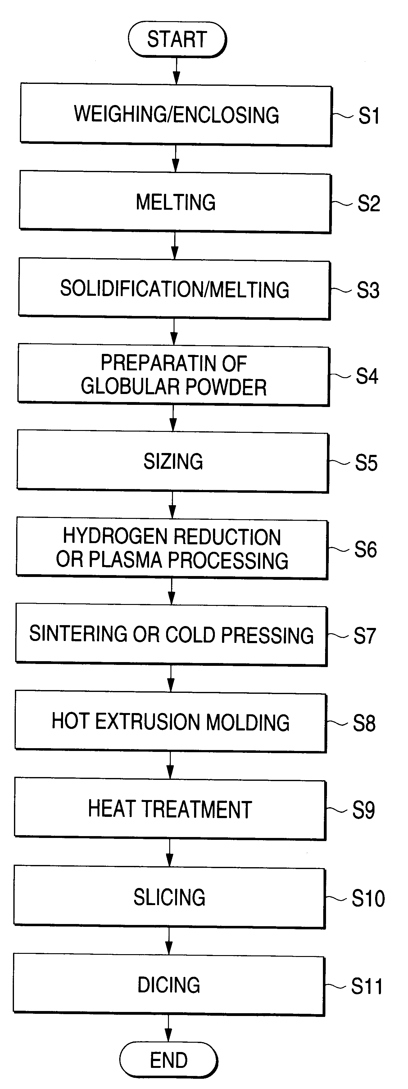
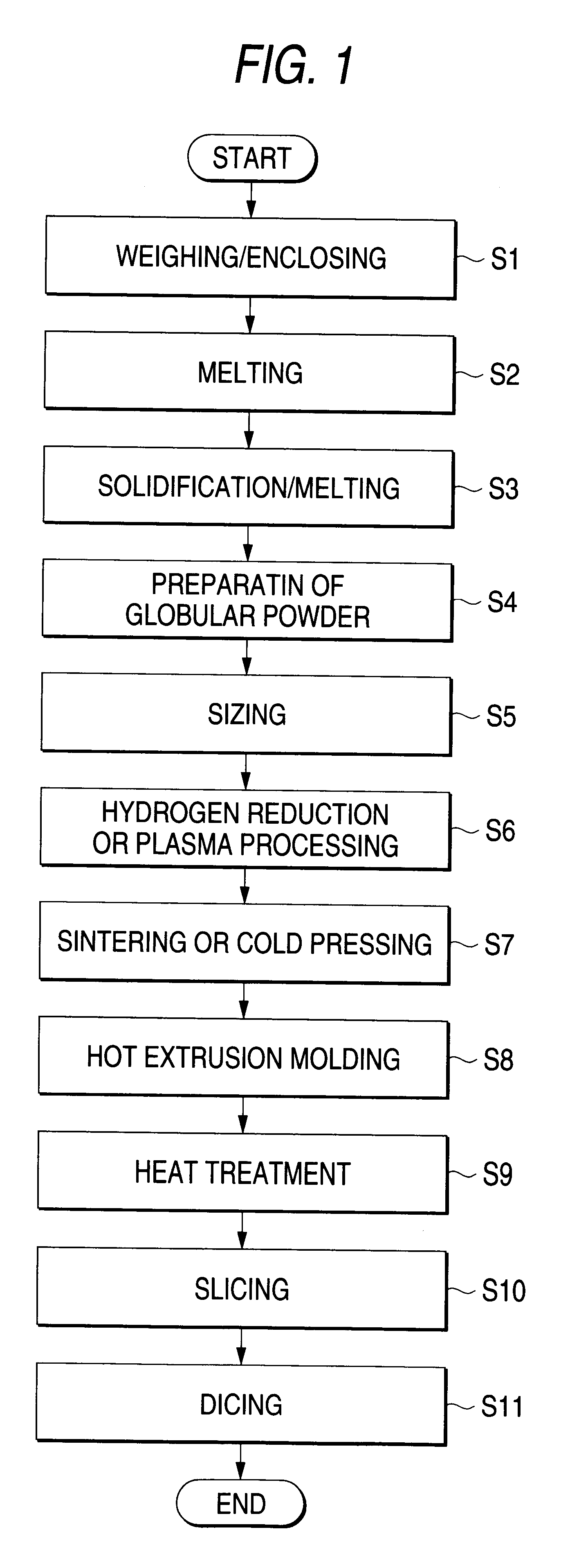
FIG. 1 is a flow chart showing a method of fabricating a thermoelectric element according to the present invention.

First, at a step S1, a raw material having a predetermined composition is weighed and is enclosed in a vessel. The raw material of a thermoelectric material contains, for example, antimony (Sb) or bismuth (Bi) being a group-V element, or selenium (Se) or tellurium (Te) being a group-VI element. Since the solid solution of the group-V and group-VI has a hexagonal structure, at least two elements among Bi, Te, Sb and Se are used for the raw material. Regarding the practicable composition of the thermoelectric material, the solid solution of a mixed crystal system consisting of bismuth telluride (Bi.sub.2 Te.sub.3) and antimony telluride (Sb.sub.2 Te.sub.3) and doped with a dopant of P-type can be used as the material of a P-type element, while the solid solution of a mixed crystal system consisting of bismuth telluride (Bi.sub.2 Te.sub.3) and bismuth selenide (Bi.sub.2 Se...

second embodiment

Next, the present invention will be described with reference to FIG. 6. The figure is a flow chart showing a method of fabricating a thermoelectric element according to this embodiment. In this embodiment, hot upset forging is implemented as the hot plastic working at the step S8. By way of example, the molded compact sintered under pressure at the step S7 is inserted into a metal mold whose side and bottom parts are fixed, and it is compression-molded by a heading punch from above. The method itself has hitherto been carried out. Since, however, the microglobular powdery thermoelectric material is employed as the material to-be-compressed, the orientation of crystal grains can be more heightened to enlarge the figure of merit.

Next, a thermoelectric module according to the present invention will be described with reference to FIG. 7.

The figure is a perspective view, partially broken away, showing the structure of the thermoelectric module which includes thermoelectric elements accor...


PUM

PropertyMeasurementUnit
grain diameteraaaaaaaaaa
grain diametersaaaaaaaaaa

Abstract

A method of fabricating a thermoelectric element of enhanced thermoelectric performance is provided by improving the preparation of thermoelectric material and employing hot plastic working in combination. The method comprises the step (a) of mixing and heat-melting a raw material of a predetermined composition; the step (b) of turning the heat-melted material 106 into microglobules by either of scattering and spraying, and then quenching the microglobules, thereby providing a globular powdery thermoelectric material; and the step (c) of plastically deforming the thermoelectric material in a hot condition, thereby to bring crystal grains of the thermoelectric material into a crystal orientation affording an excellent figure of merit.

Description

1. Field of the InventionThe present invention relates to a thermoelectric element which performs the conversion between thermal energy and electric energy, and a method of fabricating the thermoelectric element. Further, the present invention relates to a thermoelectric module which is fabricated by employing such thermoelectric elements.2. Description of the Related ArtA "thermoelectric phenomenon" is the general term of the Seebeck effect, the Peltier effect and the Thomson effect, and elements utilizing the phenomenon are called a "thermoelectric element", a "thermocouple", an "electronic cooling element", etc. The thermoelectric phenomenon was originally discovered between different kinds of metals, but in recent years, thermoelectric materials of semiconductors have come to be obtained, and conversion efficiencies not observed with metal materials have come to be attained. Elements employing the thermoelectric semiconductor materials are structurally simple, are easy of handli...

Claims


Application Information

Patent Timeline
Patent Type & Authority Patents(United States)
IPC IPC(8): H01L35/34H01L35/00B22F9/08B22F9/10H01L35/16H01L35/32
CPCH01L35/34H10N10/01
Inventor KAJIHARA, TAKESHIKONISHI, AKIOLEE, YONG HOONSASAKI, KIYOHARUTOMITA, KENICHIKAJIURA, TAKEJI
Owner KOMATSU LTD
Why Eureka
Try Eureka