Cap piercing station for closed container sampling system

a sampling system and cap technology, applied in the field of clinical chemistry sampling and analysis systems, can solve the problems of motion errors, stalling the stepper motor drive, and the type of piercing blade with an x-shaped cross-section

Inactive Publication Date: 2003-09-30
BECKMAN COULTER INC
View PDF28 Cites 50 Cited by
  • Summary
  • Abstract
  • Description
  • Claims
  • Application Information

AI Technical Summary

Benefits of technology

The cap piercing station of the present invention is further designed to work with handling racks that contain different sized containers and employs a cap presence sensor for detecting whether a cap or stopper is present at the top of a container for piercing. It also utilizes a shuttle mechanism for washing the blades between each piercing operation to eliminate carry-over contamination between sample containers. In addition, it incorporates a hydro-pneumatic lubrication and washing mechanism for lubricating and washing the blade between each piercing operation. The piercing station is also well-suited for use in an existing CTS system.
The major unique and novel features of the cap piercing station of the present invention include the design and construction of piercing blades with an H-shaped cross-section, the use of a cap presence sensor, the ability to handle various sized containers, and the design and construction of the automated washing and lubrication mechanism for washing and lubricating the blades between piercing operations to prevent contamination caused by carry-over of samples.
Such an arrangement has been found to provide a number of advantages. As explained in greater detail below, the new piercing blades with an H-shaped cross-section are well-suited for piercing thick caps or stoppers made of rubber or like materials. A sampling probe can be easily inserted into the H-shaped cut made on the cap or stopper, thereby reducing motion errors and avoiding stalling the stepper motor drive. The blades and probe can also be easily withdrawn without lifting up the sample containers. The eye-shaped opening made by the insertion of the probe also provides adequate ventilation to maintain a proper pressure profile inside the container. It also avoids the problem of metallic foil closure, thereby eliminating any false level sense when the probe is inserted into the container through the pierced cap or stopper.

Problems solved by technology

However, there are several disadvantages of this conventional type of piercing blade with an X-shaped cross-section.
One of the major disadvantages of the conventional type of a piercing blade with an X-shaped cross-section is that it is not suitable for piercing thick (i.e., approximately 3 / 8") caps or stoppers that are made of rubber material or the like.
When inserting a sampling probe into the X-shaped cut made on the cap or stopper, the probe requires too much force to penetrate, resulting in motion errors and stalling the stepper motor drive.
In addition, during withdrawal of the blades and the probe, the container tends to be lifted up together with the blades or probe and is hard to be held down.
Another disadvantage of this conventional type of a piercing blade with an X-shaped cross-section is that when a sample probe is subsequently inserted through the X-shaped cut left on the cap or stopper, the sample probe tends to re-seal the cap or stopper.
This changes the pressure profile inside the sample container (depending on the amount of sample in the container) which can compromise the aspiration of the sample and the clot detection system that relies on detecting pressure variations during the aspiration cycle.
A further disadvantage of this conventional type of piercing blades with an X-shaped cross-section is that a false level sense may be produced when a probe is inserted into the container through a pierced cap or stopper.
When the sampling probe later passes through the cap or stopper to reach the sample, it often touches the foil and thereby triggers a capacitance shift, which produces a false level sense that causes the system to believe that the sample fluid level is reached before the sample probe really reaches the fluid level.

Method used


Image

  • Cap piercing station for closed container sampling system
  • Cap piercing station for closed container sampling system
  • Cap piercing station for closed container sampling system

Examples


Embodiment Construction

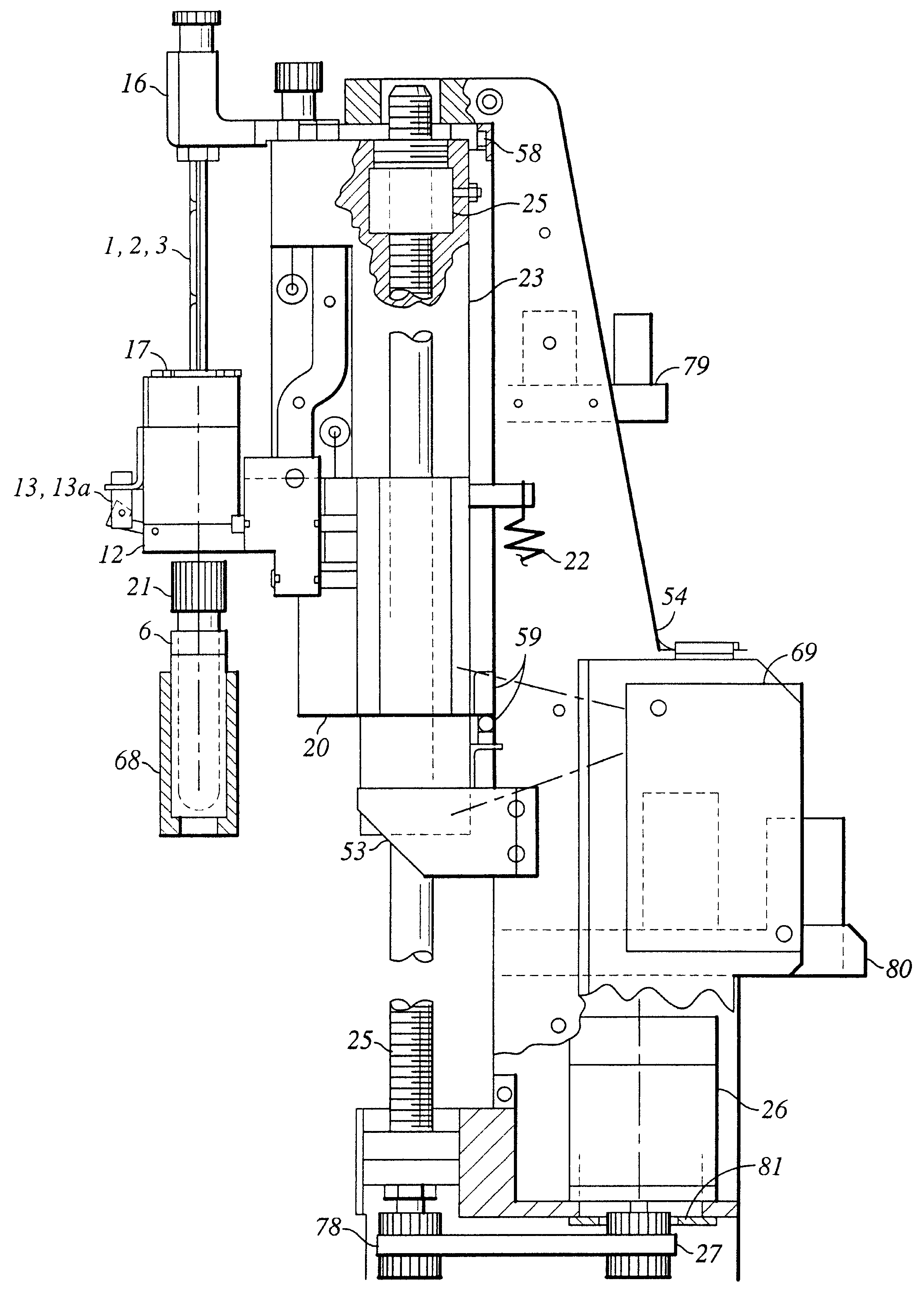
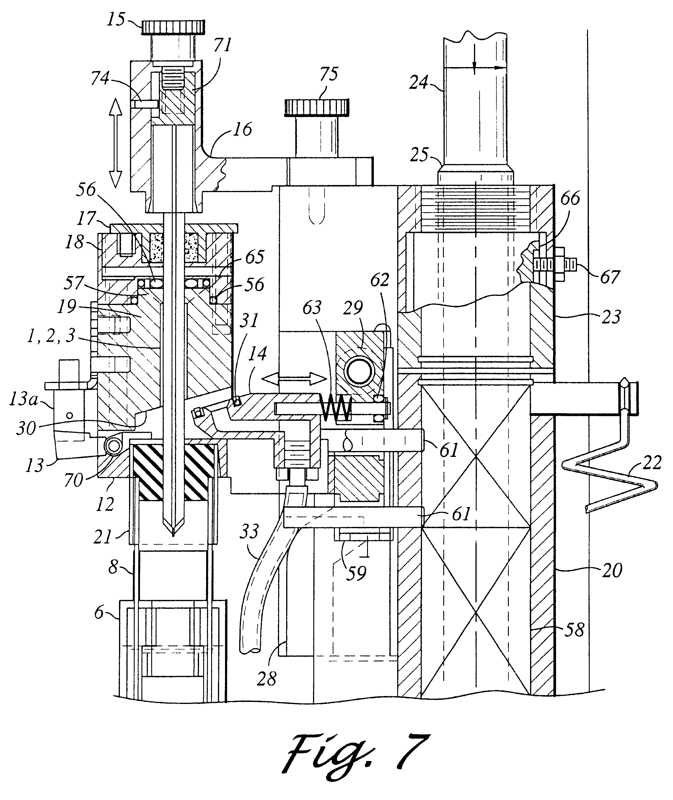
The present invention provides a piercing station for a closed container sampling system, such as a clinical chemistry analyzer.

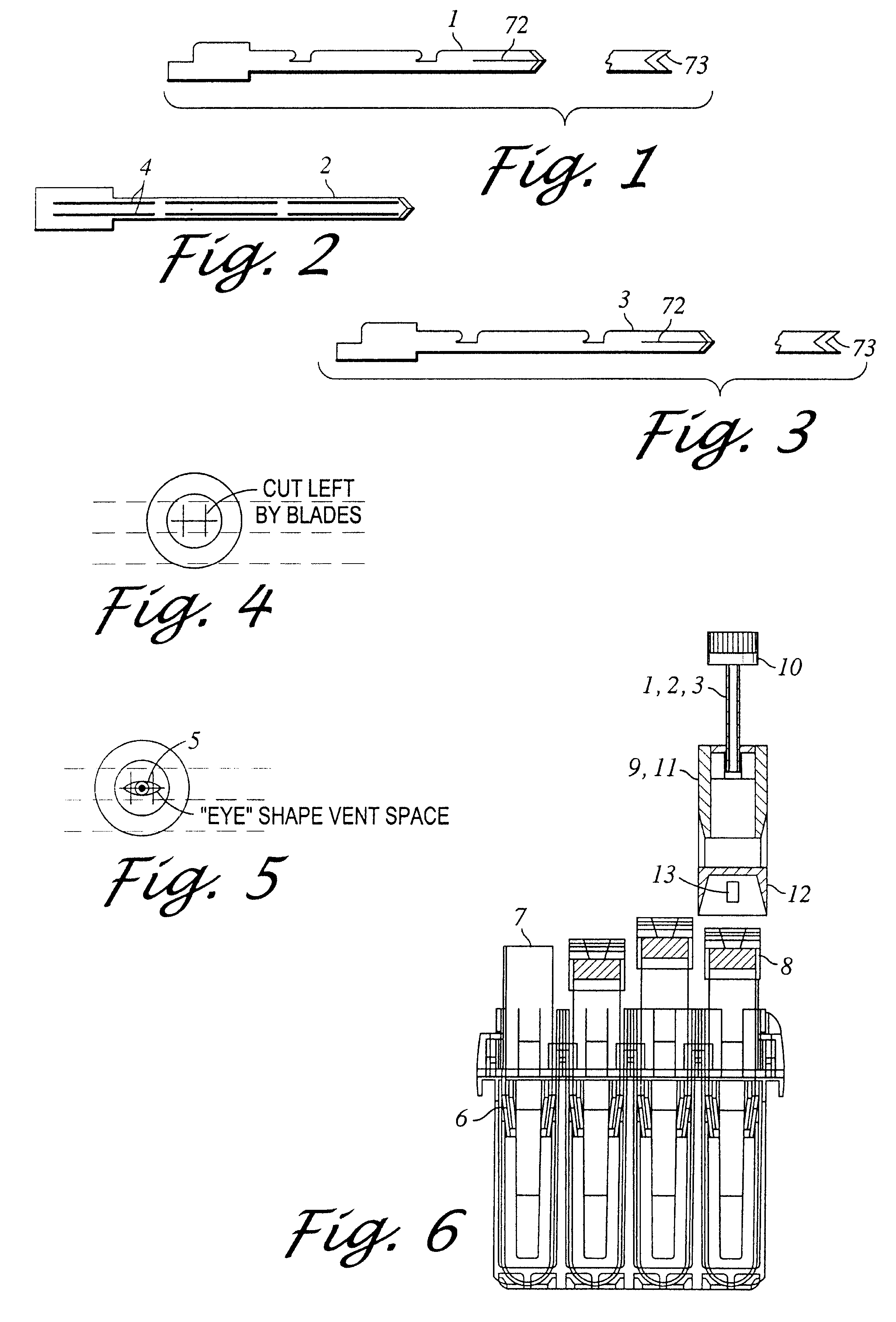
Referring to FIGS. 1, 2, and 3, there are shown three blades for assembling the new piercing blades with an H-shaped cross-section, including a first cross blade 1, a center blade 2 and a second cross blade 3. The center blade 2 has two parallel rows of lengthwise slots 4 for insertion of the two cross blades 1 and 3, respectively. Cross blades 1 and 3 are locked into these slots 4 of the center blade to assemble the new piercing blades. When assembled, the center blade 2 is on a plane perpendicular to the two cross blades 1 and 3, such that the assembled piercing blades have a modified, generally H-shaped cross-sectional configuration. In this arrangement, the center blade 2 and the cross blades 1 and 3 reinforce each other, forming a composite blade assembly, which is stiff and strong enough for piercing thick rubber caps or stoppers of the sample contain...


PUM

PropertyMeasurementUnit
widthaaaaaaaaaa
heightaaaaaaaaaa
pressureaaaaaaaaaa

Abstract

A piercing station for piercing sample container caps or thick stoppers. The piercing station has a structural frame with two vertical guide rods. A carriage assembly is slidably mounted on the guide rods and is further driven to move up and down along the guide rods. The carriage assembly carries a blade holder, which in turn holds a piercing blade assembly. The blade assembly includes a center blade and two cross blades interlocked together, such that the blade assembly has a generally modified "H"-shaped cross section for piercing a cap on the sample container. Lubricant left in or on the sample container cap by the piercing station reduces the force required by the sample probe to penetrate thick stoppers for sample aspiration and level sensing. The "H"-shaped cut helps to equalize the pressure in the sample container during sampling, so that clot detection is more effective.

Description

1. Area of the ArtThe present invention relates generally to closed container sampling systems, such as clinical chemistry analyzers, and, more specifically, to piercing stations for a closed container sampling system.2. Description of the Prior ArtClinical chemistry sampling and analyzing systems often use closed containers to contain samples to be analyzed. One of the initial and necessary functions of such sampling systems is to pierce the cap or stopper on closed containers in which the samples are contained to obtain an opening on the cap or stopper for the subsequent insertion of a sampling probe. This cap piercing function is often performed by a cap piercing station of the sampling system.In conventional sampling systems, the cap piercing station often employs piercing blades that have an X-shaped cross-section. This type of conventional piercing blade with an X-shaped cross-section appears to be able to pierce through caps or stoppers that are relatively thin. However, ther...

Claims


Application Information

Patent Timeline
Patent Type & Authority Patents(United States)
IPC IPC(8): G01N1/00G01N35/10G01N1/10
CPCG01N35/1079
Inventor GOODALE, DAVID L.ROBINS, WILLIAM M.KATZMANN, STEVEN P.
Owner BECKMAN COULTER INC
Why Eureka
Try Eureka