Method of defining and forming membrane regions in a substrate for stencil or membrane marks

a technology of membrane region and substrate, applied in the field of substrate formation, can solve the problems of single wafer process, single wafer process, and inability to produce vertical profiles in only one direction, and achieve the effect of reducing the cost of dedicated rie system, and reducing the cost of rie system

Inactive Publication Date: 2003-10-21
PHOTRONICS INC
View PDF15 Cites 7 Cited by
  • Summary
  • Abstract
  • Description
  • Claims
  • Application Information

AI Technical Summary

Problems solved by technology

The wet etch either leaves tapered profiles (from the crystalline silicon (100) planes) which reduce the useable area of the mask, or requires silicon (110) wafers that etch along the crystal planes to leave vertical strut profiles, but are more expensive and produce vertical profiles in only one direction.
However, the process in Mogab takes several hours per substrate (and usually is a single wafer process) which is expensive in a dedicated RIE system.
This, however, limits the choice of substrate and membrane materials and is rarely used in practice.

Method used


Image

  • Method of defining and forming membrane regions in a substrate for stencil or membrane marks
  • Method of defining and forming membrane regions in a substrate for stencil or membrane marks
  • Method of defining and forming membrane regions in a substrate for stencil or membrane marks

Examples


Embodiment Construction

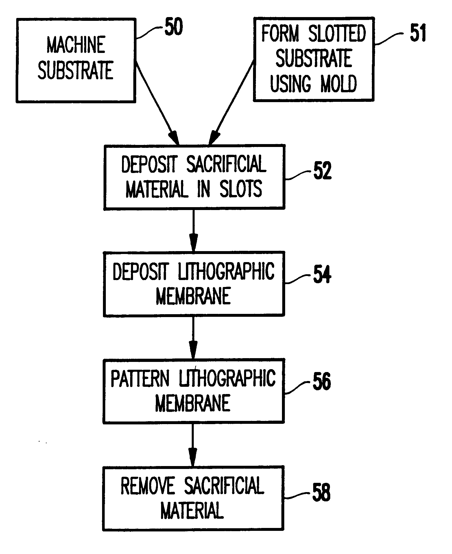
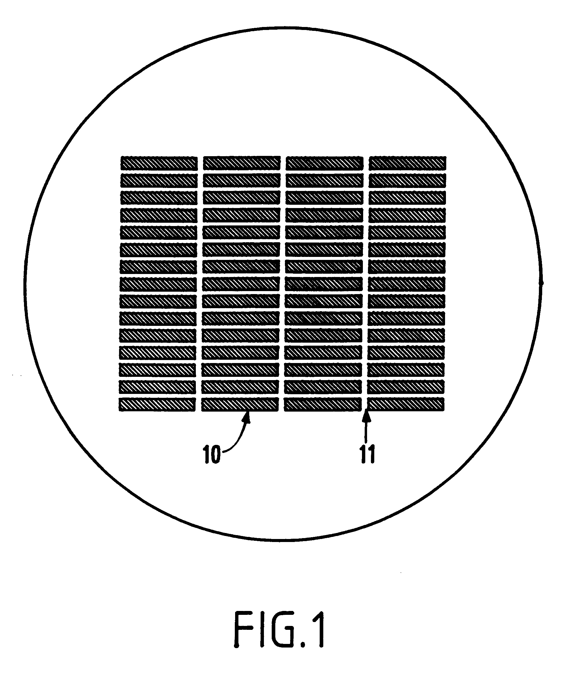
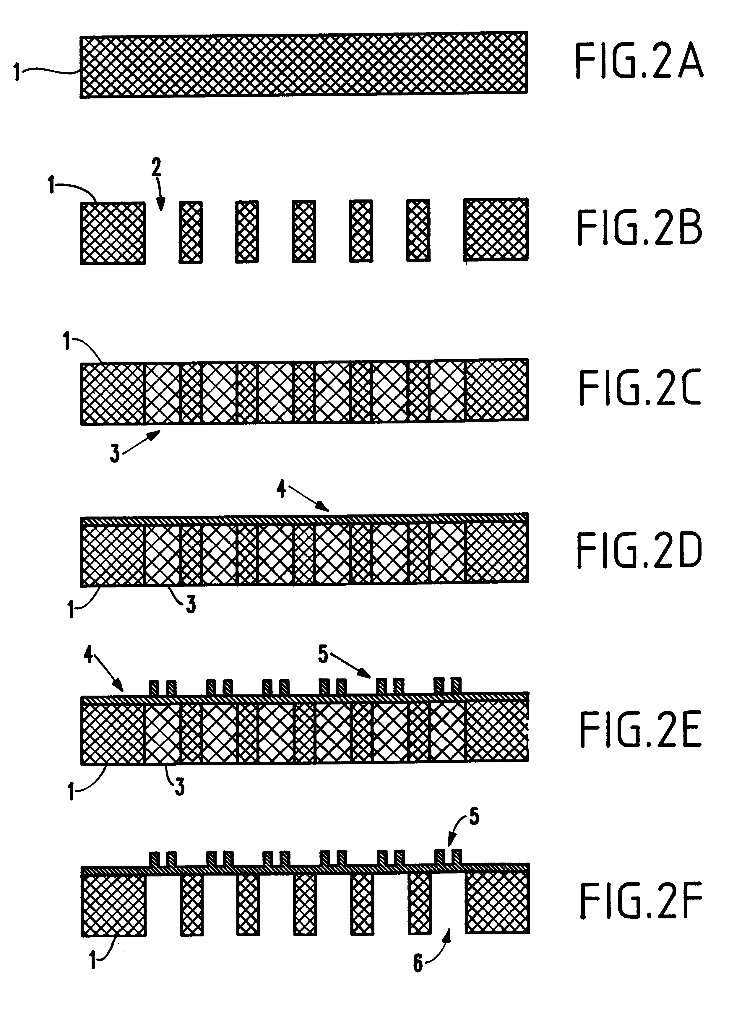
FIGS. 2A-2F illustrate a first embodiment of the invention that begins with a substrate 1 of the strut material 11 (silicon, SiC, diamond or diamond-like-carbon (DLC), polymer, or other), as shown in FIG. 2A. The substrate 1 is mechanically machined to create slots 2 through the substrate 1, as shown in FIG. 2B. Mechanical machining is distinguished from chemical or reactive ion etching in that mechanical machining involves application of a cutting tool against the substrate 1. The slots 2 have the dimensions of desired opening for the membrane subfields 10.

The slots 2 are then filled with a sacrificial material 3, as shown in FIG. 2C. The sacrificial material 3 should have properties of reasonable mechanical, chemical, and thermal robustness be easily removed after mask processing is completed, and have the ability to completely fill the slots. Alternately, the sacrificial material to 3 does not need to completely fill the slots 2, so long as the sacrificial material 3 forms a cont...


PUM

PropertyMeasurementUnit
dimensionsaaaaaaaaaa
thickaaaaaaaaaa
areaaaaaaaaaaa

Abstract

A method and structure for forming subfield regions includes mechanical definition of the substrate through machining or mold forming. The subfield regions are filled with a sacrificial layer before the thin membranes are deposited. Slots are mechanically machined through a substrate (the slots have dimensions of membrane subfields) and filled with a sacrificial material. The substrate is planarized. A membrane material is deposited over the substrate and patterned. The sacrificial layer is then removed. A mold can be utilized to form the slotted substrate in place of the machining operation.

Description

1. Field of the InventionThe present invention generally relates to the fabrication of stencil or membrane masks for high-resolution lithography, and more particularly to an improved method of forming a substrate for such masks.2. Description of the Related ArtDuring the fabrication of stencil or membrane masks for high-resolution lithography, one or many membrane regions 10 are defined in a thick substrate material, as shown in FIG. 1. Small spaces or struts 11 between these membranes 10 (the membranes often referred to as membrane subfields) act as mechanical support for the thin membranes 10. It is advantageous for these struts 11 to be vertical to maximize the useable area on the mask surface. The membranes 10 are typically 1 mm.times.12 mm for e-beam projection lithography (EPL) and may be as large as 50 mm.times.50 mm for x-ray (including Extreme Ultraviolet (EUV)) or ion projection lithography (IPL). The effective field sizes are defined by the exposure system and the toleran...

Claims


Application Information

Patent Timeline
Patent Type & Authority Patents(United States)
IPC IPC(8): G03F1/14G03F1/16G03F1/20G03F1/22H01L21/027
CPCG03F1/22G03F1/20
Inventor LERCEL, MICHAEL J.
Owner PHOTRONICS INC
Why Eureka
Try Eureka