Planar waveguide dispersion compensator

a compensator and waveguide technology, applied in the direction of optical waveguide light guide, instruments, optics, etc., can solve the problems of chromatic (wavelength dependent) dispersion of optical signals propagating along a fiber, material is generally considered unsuitable for pulse reforming, and the transmission system of glass fiber pulse code modulation (pcm) is known to suffer from chromatic dispersion

Inactive Publication Date: 2003-10-21
RPX CLEARINGHOUSE
View PDF5 Cites 22 Cited by
  • Summary
  • Abstract
  • Description
  • Claims
  • Application Information

AI Technical Summary

Benefits of technology

Advantageously, the dispersion compensation mechanism provides a means of inducing a group delay dispersion opposite to that of an optical signal in a relatively compact area. This is particularly advantageous in optical networks which carry traffic at high transmission rates. In any high-bit rate environment it is highly advantageous to be able to compensate signal dispersion in a reliable and compact manner.
By compensating for dispersion in the optical layer, both passive or active dispersion compensation can be implemented i.e. the amount of compensation may be predetermined (passive) or actively adjusted. Another advantage of the invention is that the invention can be implemented in a planar optical device.

Problems solved by technology

Glass fiber pulse code modulation (PCM) transmission systems are known to suffer from chromatic (wavelength dependent) dispersion.
Such dispersion leads to optical signals propagating along a fiber being subject to delays in their propagation time along the fiber which depend on their wavelength.
This variable delay generates several problems in optical communications networks.
Although polymer materials can provide a negative dispersion of group velocity, such materials are generally considered unsuitable for pulse reforming due to size constraints in a planar waveguide device.
Conventional dispersion compensators using techniques such as stretchable chirped fibre gratings to alter the refractive index of the fibres implementing the grating are complex, expensive, and are subject to fatigue.

Method used


Image

  • Planar waveguide dispersion compensator
  • Planar waveguide dispersion compensator
  • Planar waveguide dispersion compensator

Examples


Embodiment Construction

There will now be described by way of example the best mode contemplated by the inventors for carrying out the invention. In the following description numerous specific details are set forth in order to provide a thorough understanding of the present invention. It will be apparent however, to one skilled in the art, that the present invention may be practiced without limitation to these specific details. In other instances, well known methods and structures have not been described in detail so as not to unnecessarily obscure the present invention.

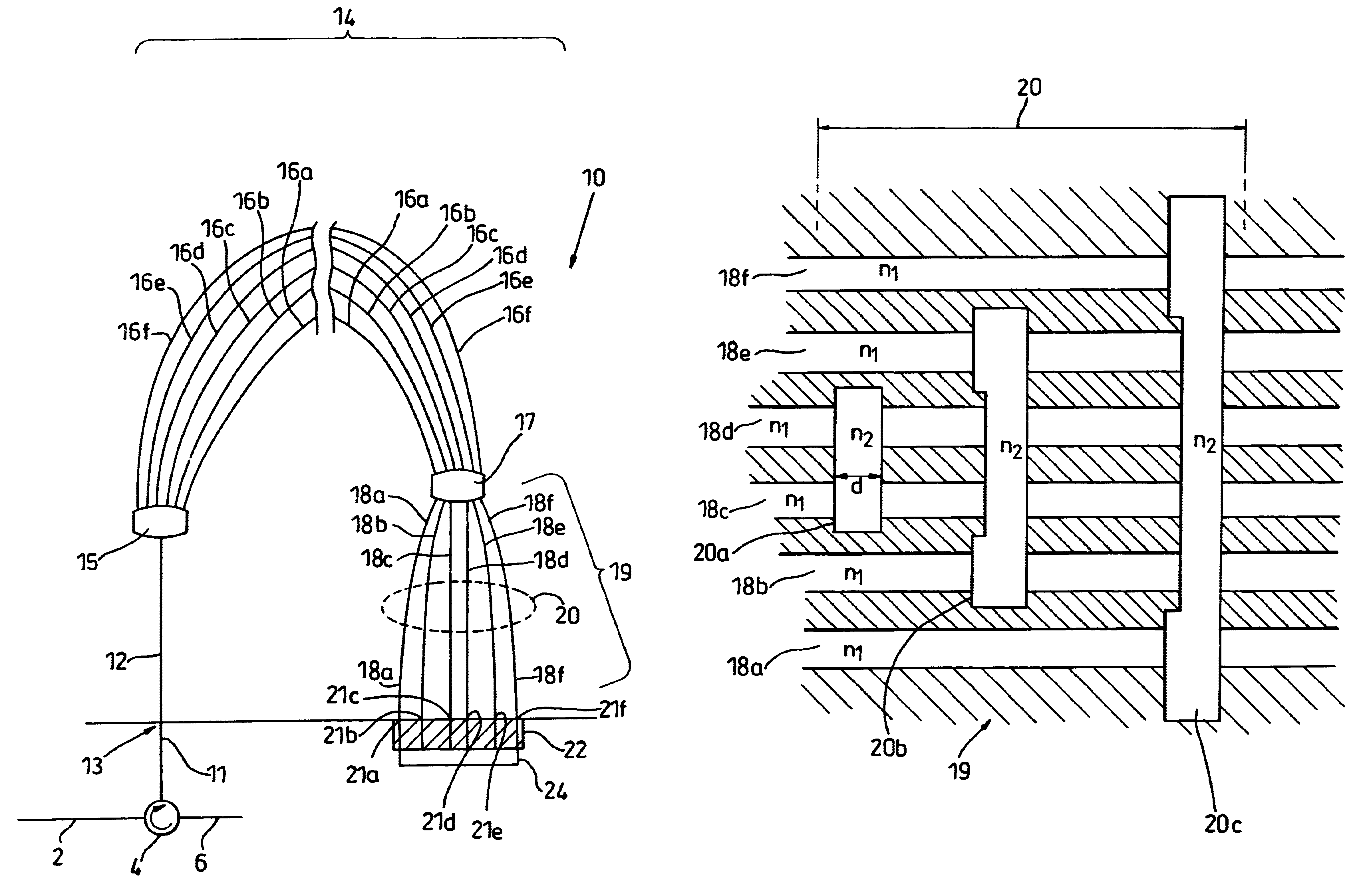
Referring now to the drawings, FIG. 1 is a sketch of a dispersion compensator 10 according to a first embodiment of the invention. In FIG. 1, the dispersion compensator 10 is implemented as a planar device.

In FIG. 1, an optical signal travelling along channel 2 passes through circulator 4 to channel 11. An optical signal returning along channel 11 is directed along channel 6. The optical signal is received by the planar waveguide dispersion...


PUM


Abstract

A planar dispersion compensator for an optical signal is provided. The compensator decomposes an inputted optical signal into N component signals separated by a fractional wavelength deltalambda. Each component signal has its path-length adjusted to induce a sufficient phase shift between input and output to change the group delay of the optical signal when recombined from each of the component signals. In this manner, pulse broadening can be compensated by selectively varying the induced phase shifts to produce the desired level of opposite group delay.

Description

The present invention relates to a planar waveguide dispersion compensator for an optical signal, and a method for compensating for dispersion in an optical signal.BACKGROUND TO THE INVENTIONGlass fiber pulse code modulation (PCM) transmission systems are known to suffer from chromatic (wavelength dependent) dispersion. Such dispersion leads to optical signals propagating along a fiber being subject to delays in their propagation time along the fiber which depend on their wavelength. This variable delay generates several problems in optical communications networks. As transmission rates increase in digital optical communications networks cheap, reliable and efficient means to implement dispersion compensation and to control the pulse profile of an optical signal during transmission through optical media are becoming highly desirable.The theoretical approach to preventing spread in a digital signal during transmission involves compensating for the variations in phase that arise from ...

Claims


Application Information

Patent Timeline
Patent Type & Authority Patents(United States)
IPC IPC(8): G02B6/34G02B6/12
CPCG02B6/12011G02B6/12019G02B6/29394G02B6/12028G02B2006/12102
Inventor THOMPSON, GEORGE HWHITEAWAY, JAMES EBRICHENO, TERRY
Owner RPX CLEARINGHOUSE
Why Eureka
Try Eureka