Circuit arrangement for operating a solenoid actuator

a solenoid actuator and circuit arrangement technology, applied in emergency power supply arrangements, circuit-breaking switches, relays, etc., can solve the problems of reduced available voltage, battery failure, and relatively inefficient operation of motors of this type, and achieve the effect of high speed

Inactive Publication Date: 2003-11-11
WABCO GMBH
View PDF11 Cites 31 Cited by
  • Summary
  • Abstract
  • Description
  • Claims
  • Application Information

AI Technical Summary

Benefits of technology

If, for example, a switched reluctance motor is used as the actuator, the first switching means can be actuated preferably in such manner that the exciter winding of the reluctance motor with stator poles closest to the rotor poles is connected to the energy supply system. In such case, the reluctance motor does not execute any substantial movement. It is an additional advantage, in this case, that the previously mentioned exciter winding has the highest inductance of all exciter windings of the reluctance motor due to the position of the rotor, so that the accumulation of the energy reserve in the energy storage can take place at a relatively high speed.
Depending on the design of the reluctance motor, or of some other electric motor, it may also be advantageous to connect several or all exciter windings at the same time to the energy supply system, such that when the first switching means has been opened, the energy quantities from several or all exciter windings is stored in the energy storage, so that the accumulation of the energy reserve in the energy storage is thus accelerated further.
It is another advantage of the invention that when an electric motor with several exciter windings is used, only a single energy storage, for example, a capacitor, is required. For this reason, the invention can be particularly economical in its implementation.

Problems solved by technology

Since the inductive behavior of the exciter winding causes a relatively slow rise in current at first, and then a relatively slow drop in current, without additional measures being taken, the operation of motors of this type is relatively inefficient.
In the power supply of solenoid actuators, such as, an electric motor or a valve actuated by an electric motor, a battery used to provide the power may have a defect, for example, a short circuit between the electrodes of the battery, resulting in a reduction in available voltage.
It is also possible that the battery may fail completely.
In such cases, however, because of the reduced operating voltage, the solenoid actuator may produce an insufficient actuating force for the situation for which it is intended.
This could have far-reaching and undesirable consequences in a safety-relevant system.

Method used


Image

  • Circuit arrangement for operating a solenoid actuator
  • Circuit arrangement for operating a solenoid actuator
  • Circuit arrangement for operating a solenoid actuator

Examples


first embodiment

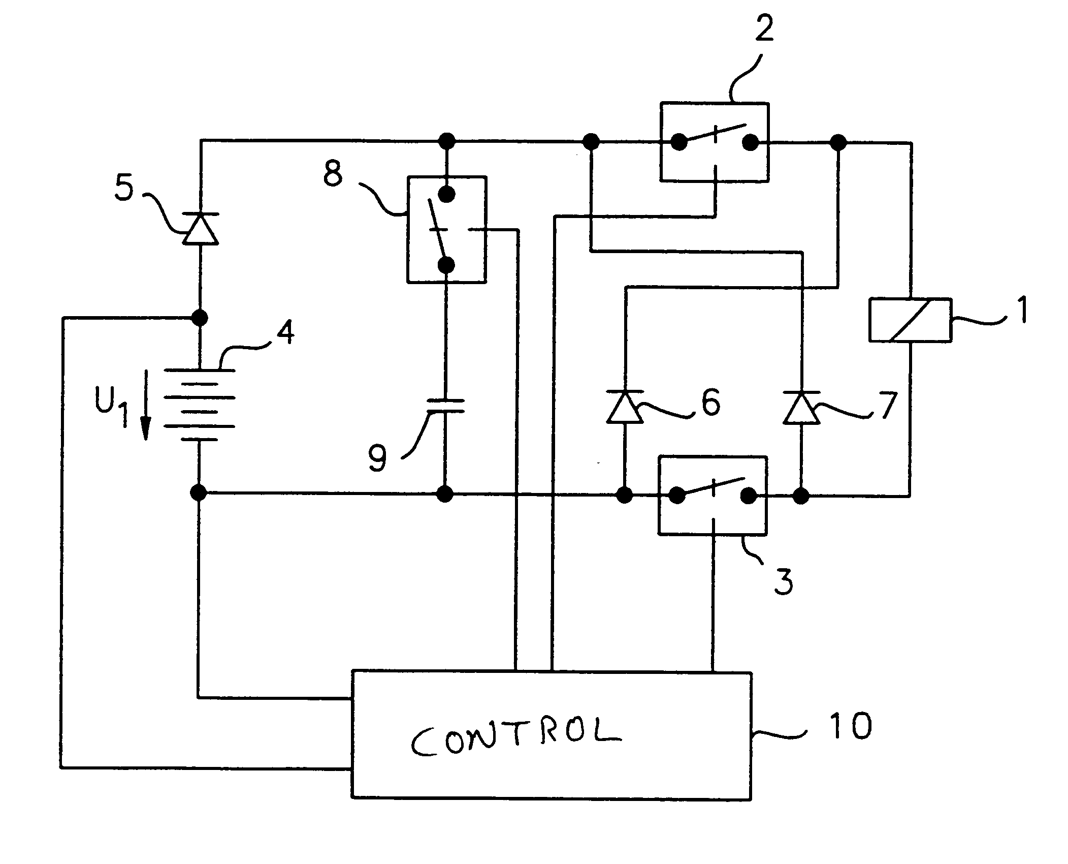
Referring now to the figures, and in particular FIG. 1, the invention is depicted, which is suitable for any type of solenoid actuator, such as, for example, solenoid valves, relays or electric motors. A solenoid actuator 1, is symbolically represented in FIG. 1, in the form of a relay coil.

The actuator 1 is connectable via a first switching device 2, 3 to an energy supply device 4, 5, 8, 9. The energy supply device 4, 5, 8, 9 is provided, in the depicted embodiment, with a battery 4, a diode 5, a switch 8 serving as a second switching device, and a capacitor 9 used as an energy storage. The battery 4 and the diode 5 serve as energy supply devices. The first switching device 2, 3 includes a first switch 2 and a second switch 3. The switches 2, 3 symbolize suitable electrical or electronic components with switching functions, such as, for example, semi-conductor switches, preferably field effect transistors. However, any kind of other component providing switching function can be use...

second embodiment

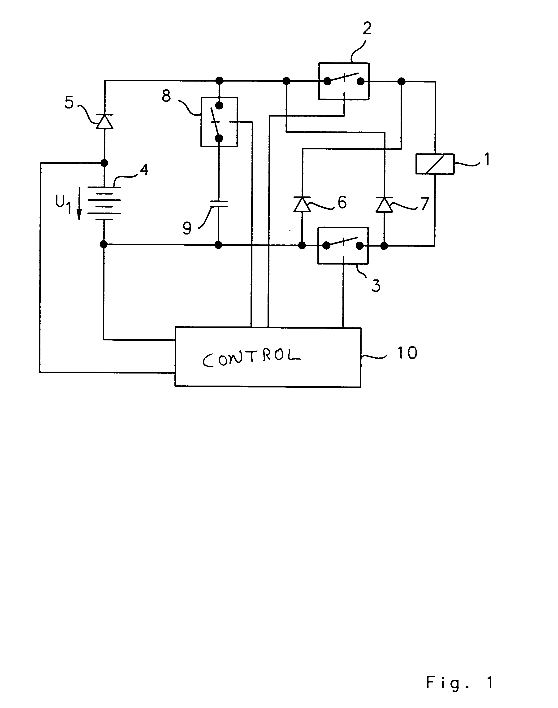
FIG. 2 shows the invention which is particularly well suited for the utilization of D.C. motors with a collector serving as the actuator, whereby the D.C. motor can be operated in both directions of rotation.

The first switching device, described with reference to FIG. 1 above, consists in this second embodiment of four switches 2, 3, 12, 13. In this case, the switches 2, 3 are arranged in a manner analogous with the circuit arrangement of FIG. 1. The switches 12, 13 are used to reverse the voltage polarity on the actuator I which, in this embodiment, is provided in the form of a D.C. motor 11. Therefore, either the switches 2, 3, or the switches 12, 13, are switched on, depending on the desired direction of rotation of the D.C. motor 11.

The energy feed-back arrangement consisting of the diodes 6, 7 in FIG. 1 includes an additional two diodes 14, 15 in the embodiment according to FIG. 2. The four diodes 6, 7, 14, 15 of the energy feed-back device are arranged in accordance with the e...

third embodiment

In FIG. 4, the invention is shown, which is particularly advantageous for use with the reluctance motor 18 described with respect to FIG. 3. In FIG. 4, only the exciter windings of the stator poles 21, 22, 23, 24, 31, 32, 33, 34, as well as the connecting conduits 37, 38 of the reluctance motor 18, are shown. The exciter windings are shown in the present embodiment in the form of individual coils or exciter windings 35 / 36, 43, 44, 45, for the sake of simplification.

In addition to the parts 4, 5, 6, 9, 16, 17 already explained with reference to FIGS. 1 and 2, the switches 2, 3, 12, 13, 39, 40 comprising the first switching device, and the diodes 6, 7, 14, 15, 41, 42 comprising the energy feed-back arrangement, are placed in this embodiment of the invention in a particularly advantageous manner, such that the expenditure in components is relatively lower than the complexity of the actuator 1, 18 employed in the embodiment. In particular, two switches and two diodes are not required fo...


PUM


Abstract

A circuit arrangement for operating a solenoid actuator, for example, an electric motor provided in the form of a switched reluctance motor, permits operation of the motor in the event of malfunction or failure of part of an energy supply. The circuit arrangement advantageously includes an auxiliary battery serving as a redundance in addition to a main battery. The auxiliary battery is smaller and has a lower nominal voltage than the main battery. In order to permit continued operation of the electric motor in the event of failure, with a nominal operating voltage which is adapted to the nominal voltage of the main battery, a capacitor which can be switched on and off is connected in series to the batteries. An energy quantity can be accumulated in the capacitor by switching the current switching through an exciter winding of the electric motor in the manner of a switching regulator, whereby the nominal voltage of the capacitor finally exceeds the voltage in the auxiliary battery. When a sufficient quantity of energy has been accumulated, the electric motor can be actuated for a short time by means of the energy accumulated in the capacitor. Electrically actuated braking systems in commercial vehicles represent a significant and preferred area of application for the invention.

Description

BACKGROUND OF THE INVENTIONThe invention relates to a circuit arrangement for operating a solenoid actuator, and more particularly, a circuit arrangement in which an energy feed-back device is located between an energy supply device and the actuator for feeding back an energy quantity stored in the actuator into the energy supply -device to provide supplementary operating power as needed.A circuit arrangement of this type is disclosed, for example, in U.S. Pat. No. 5,432,420 issued to Bahn. The disclosed circuit arrangement operates a solenoid actuator provided in the form of an electric motor, in particular, a switched reluctance motor or a brushless D.C. motor. Motors of this type are provided with a stator having several exciter windings, and a rotor located therein made of a magnetic material, or one which can be magnetized. By feeding electric current sequentially to the exciter winding, a rotary field is created inside the stator which causes the rotor to rotate. In order to a...

Claims


Application Information

Patent Timeline
Patent Type & Authority Patents(United States)
IPC IPC(8): H02P25/08H02P25/02H02J9/06H02P29/032
CPCH02P25/08H02J9/06H02J7/345H02J9/061H02P29/032
Inventor GUDAT, WOLFGANG
Owner WABCO GMBH
Why Eureka
Try Eureka