Method of laser drilling

Inactive Publication Date: 2003-11-18
HITACHI SEIKO
View PDF9 Cites 20 Cited by
  • Summary
  • Abstract
  • Description
  • Claims
  • Application Information

AI Technical Summary

Benefits of technology

A CO2 laser with high pulse frequencies, that is with repetition frequencies of 20 kHz to over 100 kHz, is preferably used for the method according to the invention, so that no time loss occurs in comparison with con

Problems solved by technology

However, the forming of a laser beam of this type is very complex.
However, such optics can only be produced in a very complex way, while diaphragms cause a large part of the laser power, often

Method used


Image

  • Method of laser drilling
  • Method of laser drilling
  • Method of laser drilling

Examples


Example

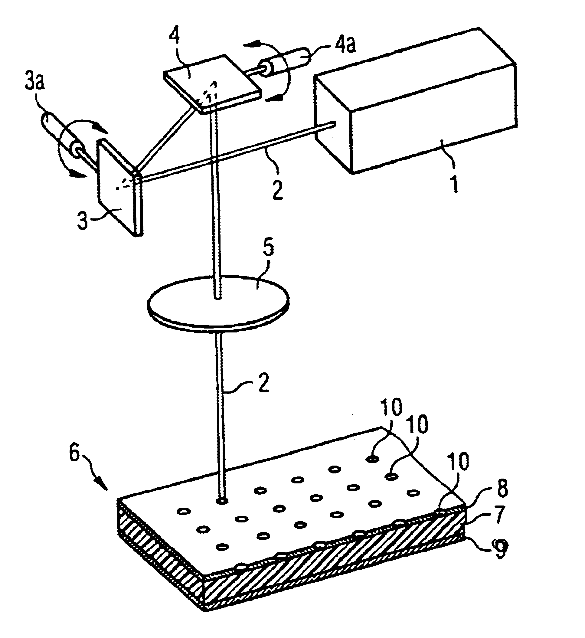
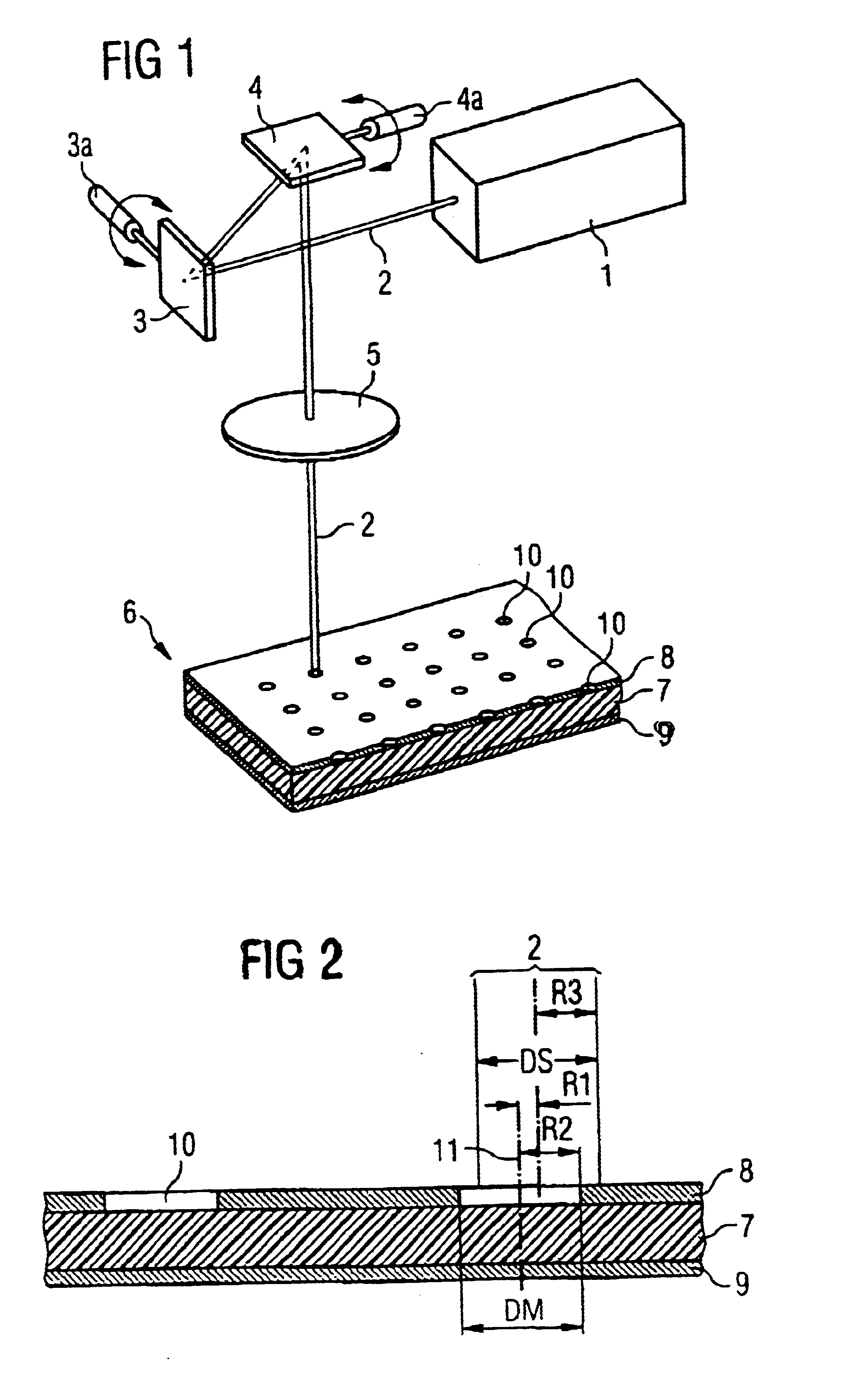
In FIG. 1, an embodiment including an arrangement of a laser as used for the drilling of holes by use of a perforated mask is shown in principle. The laser source 1 emits a pulsed laser beam 2, which is deflected at a galvanometer unit with two mirrors 3 and 4, which can be pivoted about different axes. It is then focused by using an imaging system, in the present example a telecentric lens 5, in such a way that the beam 2 impinges with a predetermined spot width on a substrate or a printed circuit board 6. The printed circuit board has a dielectric layer 7, which is located between two metal layers 8 and 9. In this case, the upper metal layer 8 serves as a perforated mask. For this purpose, the mask is provided with holes 10, which have been produced beforehand in a known way, for example also by laser drilling or by etching. Instead of the metal layer 8 solidly bonded to the dielectric layer 7, however, a loosely placed-on perforated mask in the form of a foil or the like could al...


PUM

PropertyMeasurementUnit
Fractionaaaaaaaaaa
Fractionaaaaaaaaaa
Timeaaaaaaaaaa

Abstract

In a method for the laser drilling of holes in a circuit substrate with the aid of a perforated mask, a laser beam is moved in the region of the perforated mask on a circular path. The center point of the region lies concentrically with respect to the set position of the respective hole in the mask. Further, the diameter of the region is smaller than the diameter of the hole. At the same time, the diameter of the laser beam spot is chosen to be large enough that it always covers the center point of the perforated mask during the circular motion. As a result, an energy distribution of the laser energy, which is as uniform as possible, is achieved in the region of the perforated mask.

Description

This application claims priority under 35 U.S.C. .sctn.119 on German patent application number DE 10145184.9 filed Sep. 13, 2001, the entire contents of which are hereby incorporated herein by reference.FIELD OF THE INVENTIONThe invention generally relates to a method of laser drilling of electrical circuit substrates. More preferably, it relates to a method wherein a laser beam is directed onto an intended portion of the substrate, preferably through a perforated mask close to the surface, in order to drill a hole with a predetermined hole diameter.BACKGROUND OF THE INVENTIONThe use of perforated masks when drilling holes, in particular also blind holes, in printed circuit boards and comparable substrates which serve as leadframes has long been known (U.S. Pat. No. 4,644,130A). The generally metallic perforated mask has apertures, which define by their configuration both the position and size of the holes to be drilled (known as the conformal mask). The metal layer which forms the ...

Claims


Application Information

Patent Timeline
IPC IPC(8): B23K26/00B23K26/38H05K3/00B23K26/073B23K26/388B23K101/42
CPCB23K26/386H05K3/0032H05K2203/0554B23K26/389
Inventor DE STEUR, HUBERTMAYER, HANS JUERGENMARTEN, OTTOOVERMANN, CHRISTIANPAN, WEIROELANTS, EDDYWEHNER, MARTIN
Owner HITACHI SEIKO
Why Eureka
Try Eureka