However, these systems are not suitable for immediate identity
verification.
Moreover, the use of fingerprint cards causes a considerable loss of information because registration and
processing of each and every small detail of dermal relief is limited.
However, these reflection systems also have some disadvantages due to their mode of operation.
One
disadvantage is that when a scanned finger is dry, the picture quality is reduced.
This reduced quality results in a low probability of identification.
The reason that a dry finger creates a problem is that when it touches the contact surface, the contact area is very small, making it impossible to produce a high-quality image.
It has been proven that inaccuracy of at least one micron leads to a complete loss of dactyloscopical information.
Another problem is that the low
mechanical resistance of contact surface coatings causes the
coating to come off after contact with several fingers.
Another
disadvantage of using a series of lenses is that it principally leads to a significant drop in quality because of optical distortions and aberrations introduced by the lenses.
Moreover, for each additional element introduced into the process of data transfer, additional errors are introduced.
The use of a series of lenses enlarges the size of the device and decreases the
mechanical stability and reliability.
The above-mentioned disadvantages prevent widespread use of such reflection systems, allowing only for their occasional use in instances when neither the
high security of automatic identification, nor the small dimensions of the device are prohibitive.
However, the light penetrating
system also suffers from certain disadvantages.
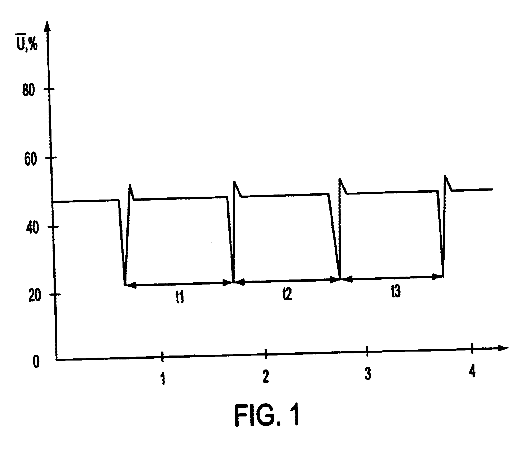
These undesirable variations are caused by the user's pulse, which provides variations in the bloodflow that affect the amount of light passing through the finger.
Such
instability of the image results in false pieces of information that decrease the quality of the image and increase the error rate.
Another
disadvantage of the light penetrating
system is the dependency of picture quality on the availability of outside natural light.
Moreover, this prior art
system does not distinguish between a live finger and a previously recorded fingerprint.
Thus, the prior art light penetrating system is vulnerable to breach by a counterfeit image, making the system undesirable for use in code-locks and other security or
access control systems.
Such devices are characterized by small dimensions, compactness, high reliability and an uncomplicated structure.
Devices using
fiber optics for direct transmission of the image (without scale
adaptation) are suitable for only rather small
skin areas, and thus are insufficient for automatic identity verification.
However, the
engineering of photosensitive units with a
diagonal of 16-24 mm, in addition to using fiber optic entry and charge transfer devices for the complete image, encounters technically difficult problems at the present time.
However, devices of this type cannot have a compact design.
Moreover, the maximum resolution decreases to approximately five lines per
millimeter, consequently raising the probability of fingerprint misidentification.
Therefore, these devices are not suitable for practical use.
The above-described disadvantages of the prior art
optical scanning identification devices and methods cause such devices and methods to be significantly limited in their potential use in automatic dactyloscopical identification processes due to a
high probability of error, in a field where errors are critical.
Of course, the Full Frame CCD can not be exposed to permanent lighting through the object, because then the formation and read out of the pictures take place simultaneously, leading to an overlap of the pictures.
Further, Full Frame CCD devices distort less information, as compared to devices utilizing other methods of charge shifting.
As noted above, Full frame CCDs may not be used in devices working in permanent lighting, because the formation and read out of the pictures take place simultaneously leading to an overlap of the pictures.
As a result, it is impossible to
gain clear pictures.
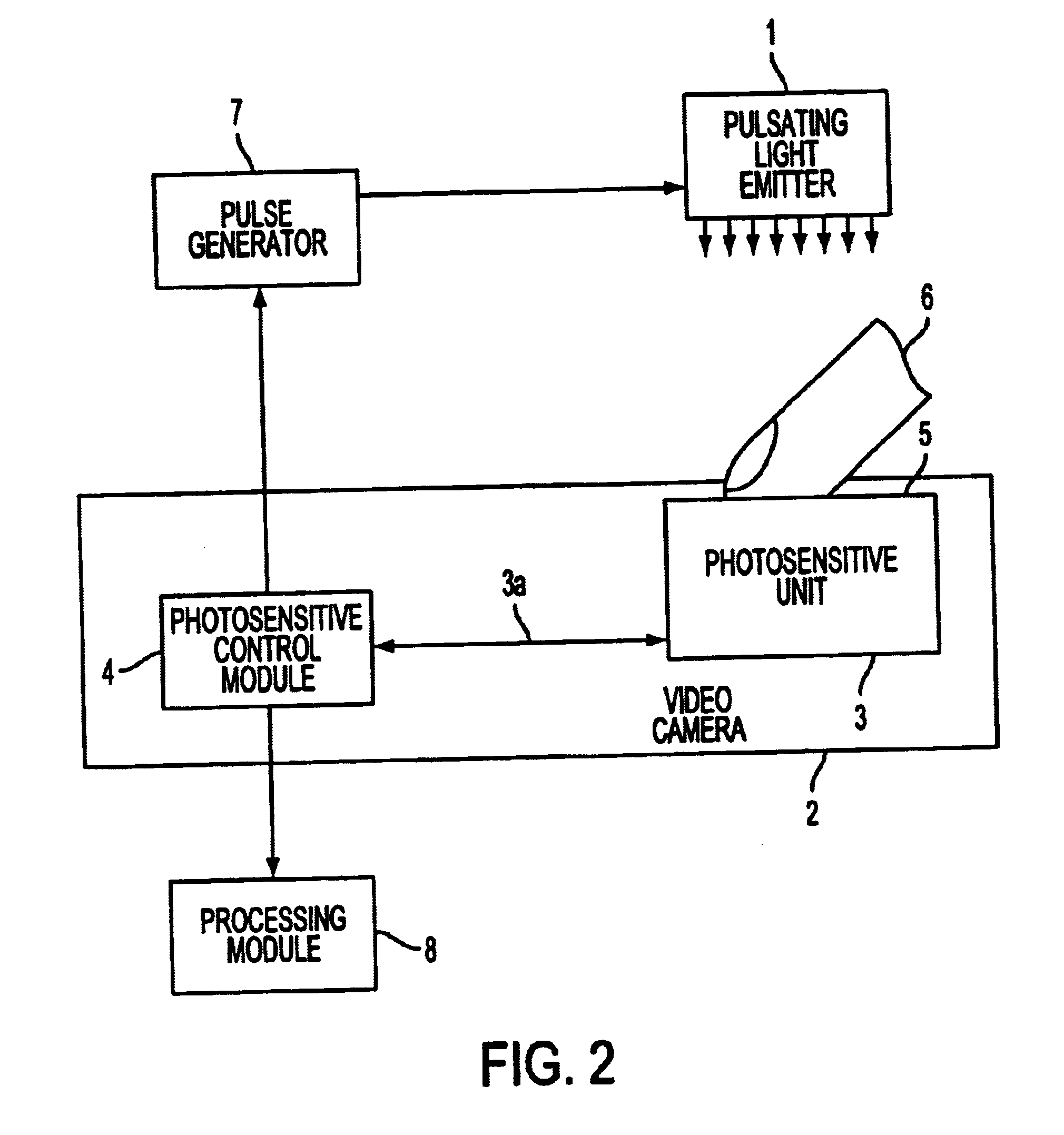
Second, a pulsating light which operates lower in the
visible range (400-800 nm) can be ergonomically less desirable because low light pulses are not good for human eyes.
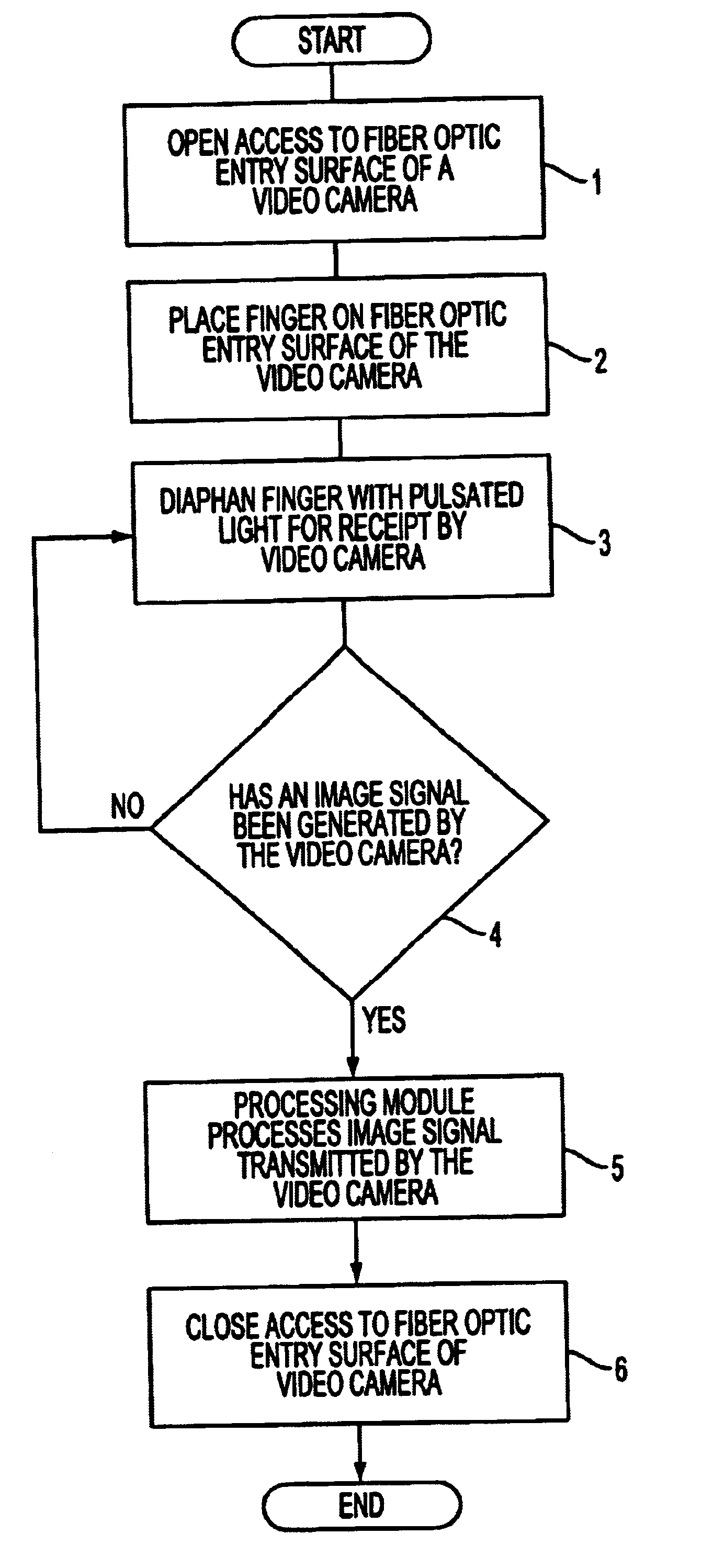
Due to a fast picture formation process, the
blood flow in the user's finger and the changes in the background lighting have almost no effect on the stability of the video
signal.

